


Synchronous Motors: Design, Operation, and Applications
Single‑Phase Synchronous Motors
Compact single‑phase synchronous motors are ideal for precision‑timing devices such as quartz clocks and tape players. While battery‑powered quartz clocks are ubiquitous, the AC‑line version offers superior long‑term accuracy because power‑plant operators actively maintain the grid frequency. If the frequency dips, operators compensate to keep clocks running precisely.
Large vs. Small Synchronous Motors
When the power rating exceeds 10 HP (10 kW), the higher efficiency and leading power factor of large synchronous motors become especially valuable in industrial settings. These motors are typically a few percent more efficient than conventional induction motors, though they are mechanically more complex.
Because motors and generators share the same fundamental construction, a generator can function as a motor and vice versa.
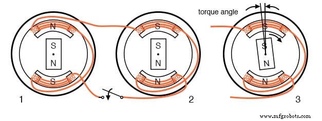
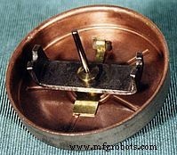
An asynchronous motor resembles an alternator with a rotating field. The figure below shows small alternators with a permanent‑magnet rotating field. The setup could be two synchronized alternators powered by mechanical drives, an alternator coupled to a synchronous motor, or two motors energized from an external source.
The key requirement is that all rotors operate at the same nominal frequency and remain in phase—i.e., they are synchronized. The synchronization procedure is:
- Open the switch.
- Drive both alternators at the same mechanical speed.
- Advance or retard the phase of one unit until the AC outputs are in phase.
- Close the switch before any drift occurs.
Once synchronized, the alternators are locked together, requiring substantial torque to desynchronize one from the other.
Synchronous motor running in step with the alternator
Accounting for Torque with Synchronous Motors
Applying additional torque in the direction of rotation to one of the rotating alternators advances its rotor relative to the stator magnetic field while still synchronized. The rotor then delivers energy to the AC line like an alternator. Conversely, adding a load such as a brake lags the rotor, drawing energy from the AC line like a motor.
Excessive torque or drag can push the rotor beyond the maximum torque angle, causing loss of synchronization. Torque generation is only possible when synchronism is maintained.
Bringing Synchronous Motors Up to Speed
Unlike alternators, a small synchronous motor does not self‑start. It must be brought up to near‑electrical speed before it can lock onto the generator’s rotation rate. Once at synchronous speed, the motor maintains synchronism and develops torque.
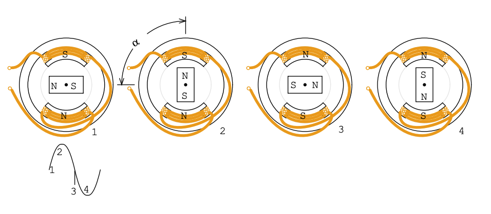
Sinewave drives synchronous motor
The motor’s rotor experiences varying torque as the stator field sweeps through its cycle. At the positive peak, the north pole of the rotor is maximally repelled; at zero volts the torque is minimal; at the negative peak the situation reverses. Over a full cycle, the torque oscillates between maximum and minimum.
Under load, the rotor lags the ideal position by an angle α. The maximum torque occurs at α = 90°, beyond which synchronism is lost. In practice, the single‑phase synchronous motor’s current pulsates while alternating polarity.
Because the rotor is a permanent magnet, it must be accelerated to near the frequency of the alternating field using an auxiliary induction motor before synchronizing.
Addition of field poles decreases the speed
A 2‑pole alternator produces a 60 Hz sine wave at 3,600 rpm (60 rev/s). Adding pole pairs reduces speed: 4‑pole → 1,800 rpm; 12‑pole → 600 rpm. Multi‑pole synchronous motors are more efficient and have higher torque.
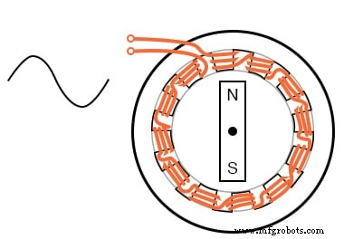
One‑winding 12‑pole synchronous motor
Rather than winding 12 coils for a 12‑pole motor, a single coil is interdigitated with twelve steel pole pieces. During one mechanical rotation, the permanent‑magnet rotor encounters six pole pairs, resulting in a speed one‑sixth of that of a 2‑pole motor.
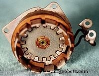
Reprinted by permission of Westclox History at www.clockHistory.com
The stator of the Westclox 12‑pole synchronous clock motor is constructed with a single coil, making it economical for low‑torque applications. The 600 rpm motor drives reduction gears that move the clock hands.
Q: If the Westclox motor were to run at 600 rpm from a 50 Hz source, how many poles would be required?
A: A 10‑pole motor (5 pole pairs) would rotate at 50 Hz ÷ 5 = 10 rev/s, or 600 rpm.
Reprinted by permission of Westclox History at www.clockHistory.com
The rotor combines a permanent‑magnet bar with a steel induction‑motor cup. The induction cup enables self‑starting; earlier designs omitted this component.
3‑Phase Synchronous Motors
A 3‑phase synchronous motor generates an electrically rotating field in the stator. These motors are not self‑starting from a fixed 50 or 60 Hz supply and typically employ an electromagnet rotor rather than a permanent magnet for multi‑horsepower units.
Large industrial synchronous motors outperform induction motors in efficiency and can correct a lagging power factor because of their leading power factor. The rotor speed in rpm is given by S = f × 120 / n, where f is line frequency (Hz) and n is the number of pole pairs.
A 4‑pole per phase motor runs at 1,800 rpm on 60 Hz and 1,500 rpm on 50 Hz. When the stator phases are energized sequentially (ϕ‑1, ϕ‑2, ϕ‑3), the resulting magnetic field rotates smoothly rather than in discrete steps.
Large synchronous motors use slip‑ring‑fed electromagnets and are self‑started by embedded squirrel‑cage conductors. The rotor is energized only after near‑synchronous speed is achieved.
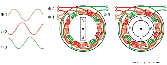
Three‑phase, 4‑pole synchronous motor
Small Multi‑Phase Synchronous Motors
Small multi‑phase synchronous motors are started by gradually ramping the drive frequency from zero to the operating frequency. The drive signals are typically generated electronically; in most cases they are sine waves, but square waves may be used in less demanding applications.
These motors are commonly known as brushless DC motors. True synchronous motors are driven by sine waveforms, while two‑ or three‑phase drives require stator windings accordingly.
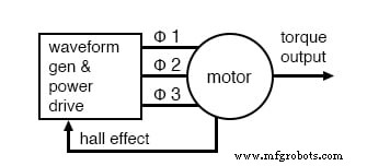
Electronic synchronous motor
The block diagram shows the drive electronics for a low‑voltage (12 V DC) synchronous motor. The motor contains an integrated position sensor that outputs a low‑level signal proportional to rotational speed.
Position sensing options include Hall‑effect devices for commutation timing, high‑resolution resolvers, inductosyn magnetic encoders, or optical encoders. For constant, accurate speed (e.g., disk drives), a tachometer and phase‑locked loop (PLL) can be employed. The PLL compares the tachometer signal to a crystal reference to maintain synchronism.
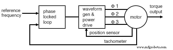
Phase‑locked loop controls synchronous motor speed
Brushless DC Motor
Motors driven by square‑wave currents, often using Hall‑effect sensors, are called brushless DC motors. They exhibit higher ripple torque than sine‑wave driven synchronous motors, which can be acceptable for many applications. However, in precision devices such as tape players, ripple torque must be minimized.
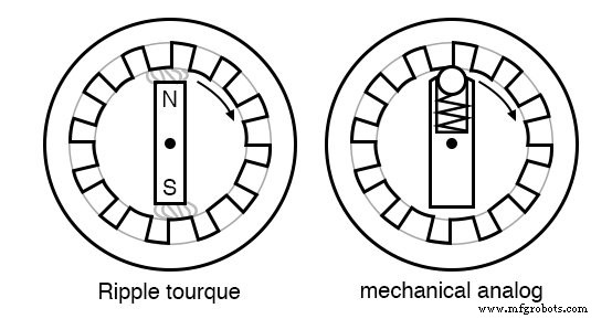
Motor ripple torque and mechanical analog
Ripple torque, or cogging, arises from magnetic attraction between rotor poles and stator pole pieces. A sine‑wave back‑EMF is produced only when the stator field is sinusoidally distributed. Distributed winding belts across many slots reduce odd harmonics, yielding a more sinusoidal field.
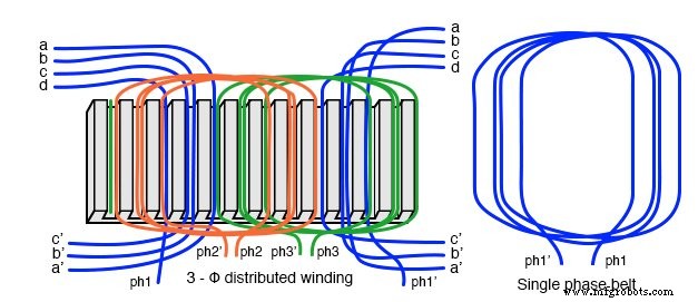
Windings distributed in a belt produce a more sinusoidal field
For a 2‑phase motor driven by sine waves, torque remains constant throughout a revolution due to the identity sin²θ + cos²θ = 1. Synchronization requires a precise rotor‑position indicator—resolvers or encoders provide this resolution.
Pulse‑width modulation (PWM) can approximate a sine wave efficiently. Each phase requires a drive circuit that supplies the waveform phase‑shifted appropriately.
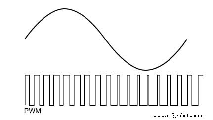
PWM approximates a sine wave
Benefits of Synchronous Motors
Synchronous motors achieve higher efficiency than induction motors and can be smaller when high‑energy permanent magnets are used. Modern solid‑state electronics enable variable‑speed operation.
While induction motors dominate railway traction, small synchronous motors inside drive wheels offer advantages in weight and efficiency. High‑temperature superconducting synchronous motors can be one‑fifth to one‑third the weight of conventional copper‑wound motors.
Experimental superconducting synchronous motors have reached the power level required to drive a naval destroyer‑class ship. Variable‑speed drives are essential in all these applications; they must also reduce supply voltage at low speed due to decreased inductive reactance.
Maximum torque occurs when the rotor lags the stator field by 90°. Exceeding this angle destroys synchronism, while a smaller lag reduces torque. Accurate rotor‑position measurement and vector phase control—implemented via a fast microprocessor and PWM—are therefore critical.
Because the stator of a synchronous motor is identical to that of an induction motor, industrial‑grade electronic speed control used for induction motors can be applied to large synchronous motors. Unrolling the rotor and stator yields a synchronous linear motor, ideal for high‑precision linear positioning.
RELATED WORKSHEET:
- AC Motor Theory Worksheet
Industrial Technology
- Synchronous Binary Counters: Design, Up/Down Operation, and Encoder Applications
- Foundations and Advancements of AC Motor Technology
- Synchronous Condenser: Enhancing Power Factor and Grid Stability
- Stepper Motors: Types, Characteristics, and Practical Applications
- Brushless DC Motors: Design, Construction, and Advanced Applications
- Wound‑Rotor Induction Motors: Design, Advantages, and Variable‑Speed Applications
- Understanding Single‑Phase Induction Motors: Types, Operation, and Efficiency Improvements
- Understanding AC Commutator Motors: Design, Types, and Applications
- Troubleshooting Wound Rotor Motors: A Practical Guide
- Electric Motor Reliability Tip: Reduce Start‑Up Cycles to Protect Your Equipment