


Synchronous Binary Counters: Design, Up/Down Operation, and Encoder Applications
What Is a Synchronous Counter?
A synchronous counter differs from an asynchronous (ripple) counter in that all output bits change state simultaneously. By tying every flip‑flop’s clock input to the same clock pulse, we avoid the ripple delay that characterizes ripple counters.
When using J‑K flip‑flops, the clock inputs are wired together so that each device receives the exact same clock edge at the same instant:
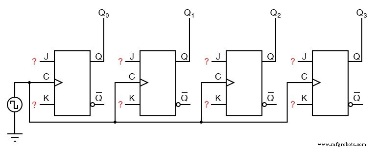
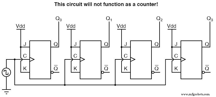
The challenge is setting the J and K inputs. To maintain the divide‑by‑two timing that produces a binary count, each flip‑flop must operate in toggle mode, which requires J=K=1 at the appropriate moments. Simply tying all J and K inputs to Vcc would cause every flip‑flop to toggle on every clock pulse, destroying the binary sequence:
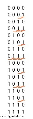
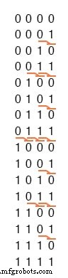
Instead, we exploit a predictable pattern in the binary sequence: a bit toggles just before all lower‑order bits are high. This pattern allows us to condition each flip‑flop’s toggle on the state of the preceding outputs.
Synchronous Up Counter
In a synchronous up counter, each J‑K flip‑flop is enabled to toggle only when all lower‑order outputs are high. The first (least‑significant) flip‑flop toggles on every clock pulse, so its J and K inputs are permanently tied high (to Vcc). The second flip‑flop toggles whenever the first output is high—no gate needed. For higher‑order flip‑flops, an AND gate feeds the J and K inputs with the conjunction of all preceding outputs.
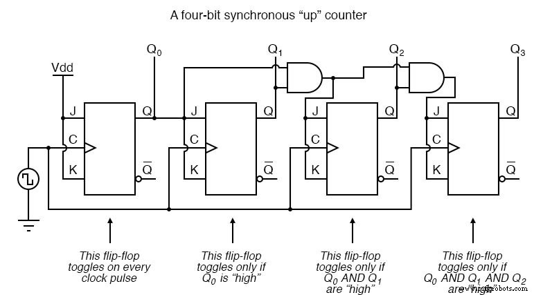
The result is a four‑bit synchronous up counter that reproduces the binary count sequence without ripple, as all stages react to the same clock edge.
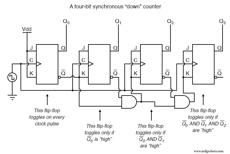
Synchronous Down Counter
Counting down reverses the toggle condition: a bit flips just before all lower‑order bits are low. The Q′ outputs of J‑K flip‑flops provide the necessary “low” signal, so each flip‑flop’s toggle is enabled when its lower outputs are low.
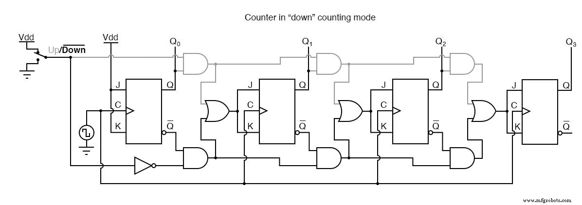
Up/Down Counter with Selectable Mode
By adding a control line that selects between the “up” and “down” AND‑gate networks, we can build a single counter that counts both directions. An OR gate then feeds the selected AND‑gate output to each flip‑flop’s J and K inputs.
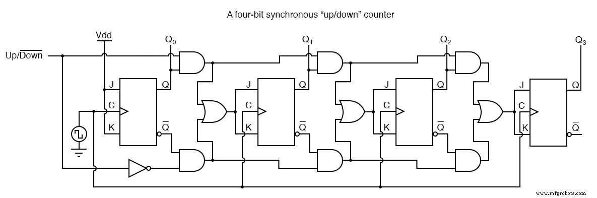
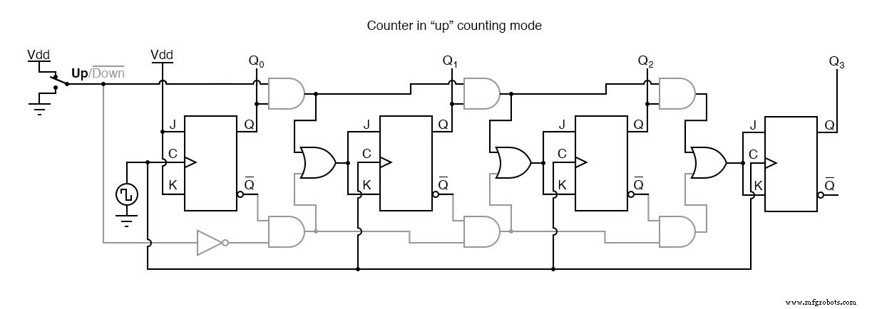
The control line toggles which AND‑gate network is active: high for up counting, low for down counting. Example diagrams show the circuit with the inactive sections shaded gray.
Practical Applications
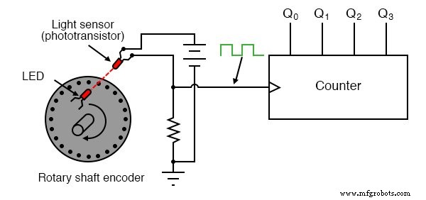
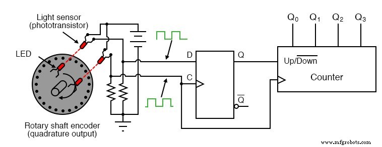
Up/down counters are indispensable in motion control. Rotary shaft encoders generate clock pulses that drive the counter to track position. When only total displacement matters, a single‑channel encoder suffices. To also capture direction, a quadrature encoder supplies two out‑of‑phase signals.
A D‑type flip‑flop distinguishes the phase relationship between the two encoder signals, setting the counter to increment or decrement accordingly.
Such circuits underpin robotics, CNC tooling, and any application that requires precise measurement of reversible mechanical motion.
Related Worksheets
- Synchronous Counter Worksheet
Industrial Technology
- 3‑Bit Binary Counter with 555 Timer and 4027 Flip‑Flops
- Designing an Asynchronous Four‑Bit Up Counter with J‑K Flip‑Flops
- Counter Modulus: Optimized Algorithms for Modern Systems
- Ring Counters and Johnson Counters: Design, Operation, and Practical Applications
- Digital Ramp (Counter) ADC: Operation, Benefits, and Limitations
- Tracking ADC: Up/Down Counter for Fast, Continuous Signal Conversion
- Synchronous Motors: Design, Operation, and Applications
- Synchronous Condenser: Enhancing Power Factor and Grid Stability
- LVDT Demodulation Explained: Rectifier-Type vs. Synchronous Techniques
- 4‑bit Counter: Efficient Binary Counting from 0 to 15