


Build a Handheld Geiger Counter Using Arduino Nano
Components and supplies
 |
| × | 1 | |||
| × | 1 | ||||
| × | 1 | ||||
| × | 1 | ||||
| × | 1 | ||||
| × | 1 | ||||
| × | 1 | ||||
 |
| × | 1 |
Necessary tools and machines
 |
|
Apps and online services
 |
| |||
 |
| |||
| ||||
| ||||
| ||||
|
About this project
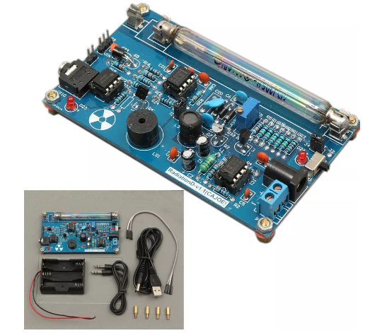
This project started after I bought a readymade Geiger counter kit from Banggood.
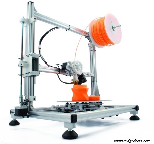
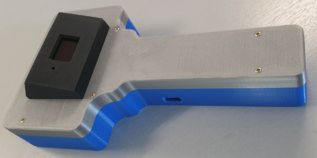
The idea was to put this kit in a 3D-printed housing so the complete working Geiger counter set could be handheld. The final result is shown below:
The design of the handheld Geiger counter is shown in the below diagram:
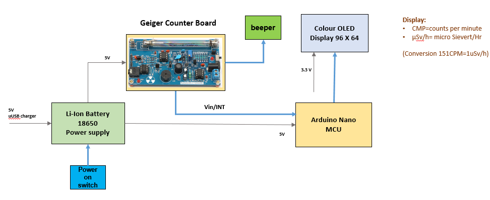
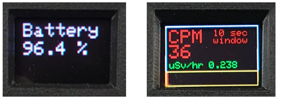
The Geiger counter is equipped with an 0.96 inch color OLED display, which informs the user about the measured CPM (measure of the detection rate of ionization events per minute) as well as the (calculated) dose equivalent in µSv/hr using a simple factor of 151 which can be found in literature for the type of Geiger-Müller (GM) tube used.
See also Wikipedia: https://en.wikipedia.org/wiki/Counts_per_minute
In fact the displayed CPM is the result of a calculation of counts for one minute, by measuring the counts per second (CPS) and storing these measurements in an array that covers the past ten second period. The total number of counts over this past 10 sec period is multiplied by 6 to obtain the CPM value.
The number of counts over the past second is used to display the momentary number of measurements through a bar graph on the OLED display. This is useful in case of high count rates, or when rapid changes of the count rate occur when the handheld counter is moved over a radiation source.
The Geiger counter is powered by a Li-ion battery type 18650, that can be charged via a micro-USB plug. The Arduino Nano USB port is also accessible for software changes. An extra buzzer is connected to the Geiger counter board to enhance the sound of the ionizations in the GM tube.
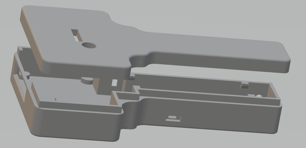
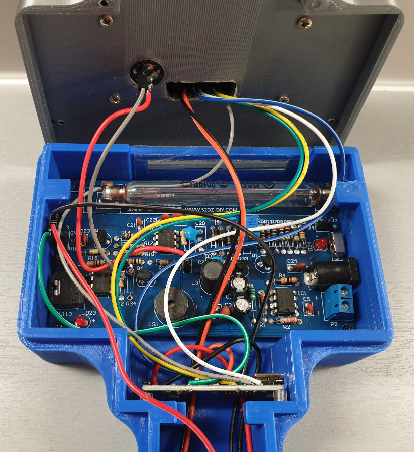
All electronics for the Geiger counter are built in the 3D-printed housing:
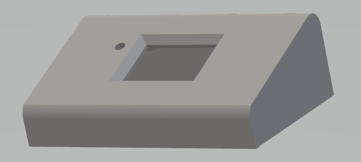
The OLED display is put in a separate box on top of the Geiger counter:
The fully assembled version:
The following materials are used:
- Arduino NANO 1 https://store.arduino.cc/arduino-nano
- Geiger Counter Kit 1 https://uk.banggood.com/Assembled-DIY-Geiger-Counter-Kit-Module-Miller-Tube-GM-Tube-Nuclear-Radiation-Detector-p-1136883.html?rmmds=search&cur_warehouse=CN
- 0.96" OLED color display 96 * 64 1 https://www.banggood.com/0_95-Inch-7pin-Full-Color-65K-Color-SSD1331-SPI-OLED-Display-For-Arduino-p-1068167.html?rmmds=search&cur_warehouse=CN
- Micro USB Charger Board 18650 Battery 1 https://www.banggood.com/5pcs-ESP32S-ESP32-0_5A-Micro-USB-Charger-Board-18650-Battery-Charging-Shield-p-1398716.html?rmmds=myorder&cur_warehouse=UK
- 3.7v 4000mAh Protected Rechargeable 18650 Li-ion Battery 1 https://www.banggood.com/4PCS-MECO-3_7v-4000mAh-Protected-Rechargeable-18650-Li-ion-Battery-p-992723.html?rmmds=myorder&cur_warehouse=CN
- Transistor BC547 1
- BUZZER -12MM 1
- Resistor 1k Ohm 1
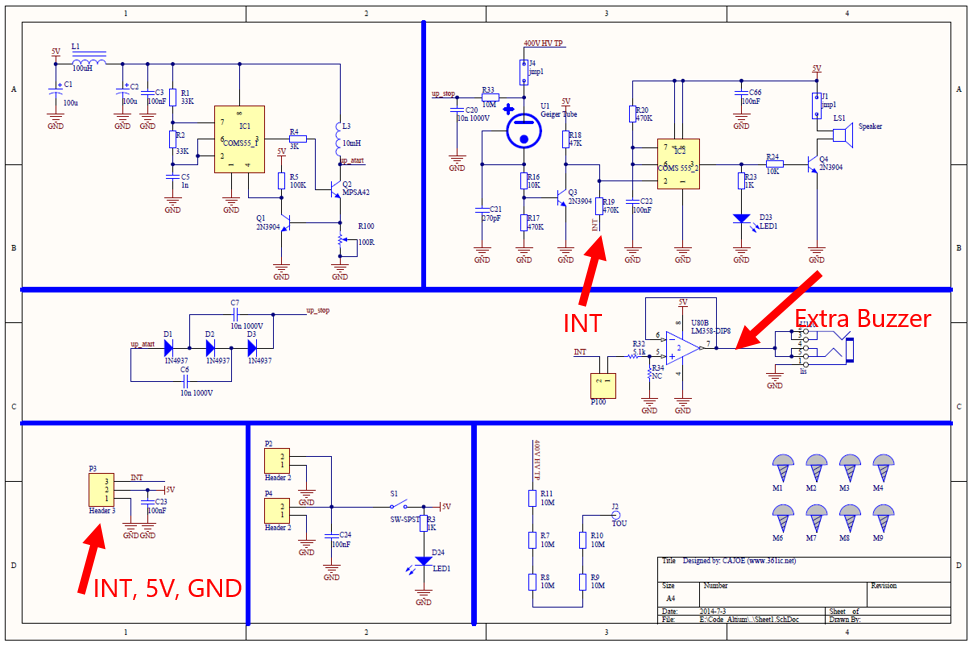
The electronic design of the Geiger counter kit is shown in the following circuit diagram:
The circuit diagram of the complete Geiger Counter setup is as follows:
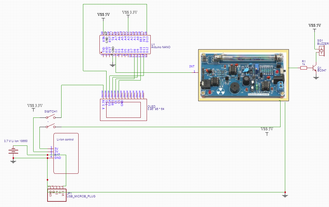
The 5V power is supplied from a rechargeable Li-Ion battery placed in a Micro USB Charger Board. The 3, 3 V for the OLED display is taken from this board.
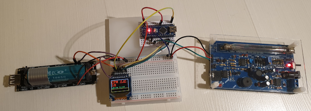
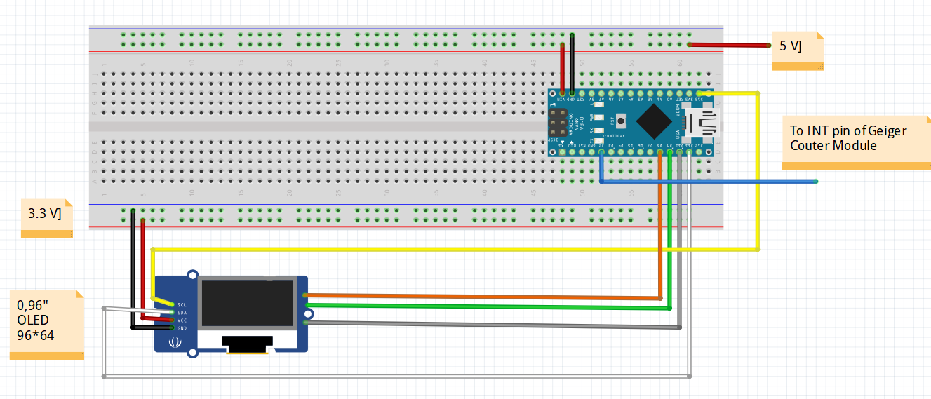
The breadboard set up used for testing and building the software with the ARDUINO IDE, is shown in the following picture:
The assembly of all mechanical and electronic parts is shown in the pictures below:
Note that the handheld Geiger counter does not have any cable connections.
For charging the 3, 7V Li-ion battery there is a separate opening in the housing for (temporarily) connecting a micro USB plug.
An additional mini USB connection is available for software updates of the Arduino Nano.
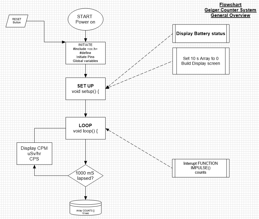
Step 3: The Software DesignThe following flowchart shows the general software design of the Geiger Counter:
The views on the 0, 96” OLED display, are:
The complete Arduino sketch is listed below:
#include <Adafruit_GFX.h>
#include <Adafruit_SSD1331.h>
#include <SPI.h>
 //Connections for the OLED display
#define sclk 13 //SCL  (blue wire)
#define mosi 11 //SDA  (white wire)
#define cs 10 //CS   (grey wire)
#define rst 9 //RES  (green wire)
#define dc 8 //DC   (yellow wire)
#define LOGtime 1000 //Logging time in milliseconds (1 second)
#define Minute 60000 //the period of 1 minute for calculating the CPM values
#define show endWrite
#define clear() fillScreen(0)
// Color definitions
#define BLACK 0x0000
#define BLUE 0x001F
#define RED 0xF800
#define GREEN 0x07E0
#define CYAN 0x07FF
#define MAGENTA 0xF81F
#define YELLOW 0xFFE0
#define WHITE 0xFFFF
Adafruit_SSD1331 display = Adafruit_SSD1331(cs, dc, rst);
int Counts = 0; //variable containing the number of GM Tube events withinthe LOGtime
unsigned long previousMillis= 0; //variablefor storing the previous time
int AVGCPM = 0; //variable containing the floating average number ofcounts over a fixed moving windo period
int TenSecCPM = 0;
int units = 0;
int tens = 0;
int hundreds = 0;
int thousands = 0;
float Sievert = 0;
int COUNTS[10]; // array for storing the measured amounts of impulses in10 consecutive 1 second periods
int t = 0;
////////////////////the setup code that follows,will run once after "Power On" or after a RESET///////////////////
void setup() {
 Serial.begin(115200);
 display.begin();
 display.fillScreen(BLACK);

 floatBattery = analogRead(A3); //(orange wire)
 floatBattPerc = 100 * (Battery/770);

 //Serial.print("battery value = "); Serial.println (Battery); Serial.print("battery percentage = "); Serial.println (BattPerc);
 display.setCursor(4,4);
 display.setTextSize(2);
 display.setTextColor(MAGENTA);
 display.println("Battery");
 display.setCursor(4,24);
 display.print (int (BattPerc)); display.print("."); display.print (int((10*BattPerc)-(10*int(BattPerc))));display.print(" %");
 delay(3000);
 display.fillScreen(BLACK);
 for(int x = 0; x < 10 ; x++) { //put all data in the Array COUNTS to 0 (Array positionsrun from 0 to 10;
 COUNTS[x] = 0; //10 positions covering a period of 10 seconds
 }

 attachInterrupt(0, IMPULSE, FALLING); //define external interrupton pin D2/INT0 to start the interupt routine IMPULSE  (green wire)

 display.drawRect(0,0,96,64,WHITE);
 display.setCursor(4,4);
 display.setTextColor(RED);
 display.setTextSize(2);
 display.print("CPM");
 display.setCursor(50,4);
 display.setTextSize(1);
 display.print("10 sec");
 display.setCursor(50,12);
 display.print("window");

 display.setCursor(4,38);
 display.setTextSize(1);
 display.setTextColor(GREEN);
 display.print("uSv/hr");

 display.drawRect(0,48, 96, 16, YELLOW);
}
////////////////////////the loop code that follows,will run repeatedly until "Power Off" or a RESET/////////
void loop()
{
 unsignedlong currentMillis= millis();
 if(currentMillis - previousMillis >LOGtime)
 {
 previousMillis = currentMillis;
 COUNTS[t] = Counts;
 for (int y = 0; y < 10 ; y++) { //add all data in the Array COUNTS together
 TenSecCPM = TenSecCPM + COUNTS[y]; //and calculate the rolling average CPM over a 10 secondperiod
 }
 AVGCPM = 6* TenSecCPM;
 TenSecCPM = 0;
 t++ ;
 if (t > 9) { t = 0 ;}

 //Serial.print ("COUNTS "); Serial.print(t);Serial.print (" = ");Serial.println (COUNTS[t]);
 display.fillRect(4,20,90,17,BLACK); // clear the CPM value field on the display
 display.setCursor(4,20);
 display.setTextColor(RED);
 display.setTextSize(2);
 display.println(AVGCPM);
 //Serial.print ("AVGCPM = "); Serial.print(AVGCPM); //Serial.print ("   CPM = "); Serial.println(CPM);
 display.fillRect(45,38,50,10,BLACK); //clear the uSv/Hr value field on the display
 display.setCursor(45,38);
 display.setTextColor(GREEN);
 display.setTextSize(1);

 Sievert = (AVGCPM /151.0) ; //Serial.print ("  Sievert = ");Serial.println (Sievert);
 units = int (Sievert); //Serial.print ("units = "); Serial.println(units);
 tens = int ((10*Sievert) - (10*units)); //Serial.print ("tens = "); Serial.println(tens);
 hundreds = int ((100*Sievert) - (100*units) - (10* tens)); //Serial.print ("hundreds = "); Serial.println(hundreds);
 thousands = int ((1000*Sievert) - (1000*units) - (100*tens) - (10*hundreds)); //Serial.print ("thousands ="); Serial.println (thousands);
 display.print (units); display.print("."); display.print (tens); display.print (hundreds);display.println (thousands);

 display.fillRect(1,49,94,14,BLACK); // clear the CPM indicator field on the display
 display.fillRect(1,49,Counts,14,RED); //fill the CPM indicator field on the display

 Counts = 0;
 }
}
//////////////////END ofLOOP////////////////////////////////////
/////////////////////////////////Hereafter follows the Function for counting the number of impulses from Geiger Counter kit
void IMPULSE()
 {
 Counts++;
 }
The most important part of the sketch is interrupt function that is called when an impulse on the GM tube of the Geiger Counter is measured that triggers the INT output of the Geigercounter (by making it LOW for a short period). The INT signal is connected to the pin D2 (the external interrupt pin INT0 of the Arduino Nano):
attachInterrupt(0, IMPULSE, FALLING);The INT signal will start the interrupt routine IMPULSE () to increase Counts with 1:
void IMPULSE() {Counts++ ; }After the lapse of 1000 milliseconds:
- the integer Counts is put back to 0
- the array COUNTS [ ] is filled with the number of counts measured during the past 1000 milliseconds
- the total number of counts over the past 10seconds is calculated by adding all the numbers from the array COUNTS [ ] and multiplied by 6 to present the CPM value on the display.
- The dose equivalent expressed in µSv/hr is calculated by division of the CPM value with151 (a value that is found in literature).
- On the colour OLED display a red bar is shown based on the value of Counts in the past second, so in fact presenting the CPS value (Counts Per Second)
The complete ARDUINO sketch for the Geiger counter comprises about 150 lines of code. The complete listing is included as part of this tutorial, the ARDUINO code (see chapter 9) is provided with an ample amount of comments.
Code
- Geiger_Counter.ino
Geiger_Counter.inoArduino
ARDUINO Sketch for the Geiger Counter running on an Arduino Nano:/*********
This project has been developed and produced by Pierre Pennings (December 2019),
This Project is about making a handheld Geiger Counter using a ready made Geiger Counter kit, in a 3D printed handheld radiation detector,
De kit is connected to an Arduino Nano that counts the number of impulses from the Geiger/Muller tube in a period of 10 seconds and then displays the average CPM (Counts Per Minute) on a 96*64 OLED color display.
The measured CPM is also displayed as micro Sievert per Hour (with a simple conversion factor of 151)
The OLED display also displays the momentary measured amount of impulses (per second) and displays the measurements as a moving red bar on the display.
The 3D printed housing contains also the 18650-Ion Lithium battery (rechargeble) which provides the 5V power to the Arduino Nano as well as the Geiger Counter kit and 3,3V for the OLED display.
A power-on swith and an external beeper complete the detector.
Upon power-on, the charging level of the 18650 battery is shown on the color display.
This code is licensed under GPL3+ license.
*********/
#include <Adafruit_GFX.h>
#include <Adafruit_SSD1331.h>
#include <SPI.h>
//Connections for the OLED display
#define sclk 13 //SCL (blue wire)
#define mosi 11 //SDA (white wire)
#define cs 10 //CS (grey wire)
#define rst 9 //RES (green wire)
#define dc 8 //DC (yellow wire)
#define LOGtime 1000 //Logging time in milliseconds (1 second)
#define Minute 60000 //the period of 1 minute for calculating the CPM values
#define show endWrite
#define clear() fillScreen(0)
// Color definitions
#define BLACK 0x0000
#define BLUE 0x001F
#define RED 0xF800
#define GREEN 0x07E0
#define CYAN 0x07FF
#define MAGENTA 0xF81F
#define YELLOW 0xFFE0
#define WHITE 0xFFFF
Adafruit_SSD1331 display = Adafruit_SSD1331(cs, dc, rst);
int Counts = 0; //variable containing the number of GM Tube events within the LOGtime
unsigned long previousMillis = 0; //variable for storing the previous time
int AVGCPM = 0; //variable containing the floating average number of counts over a fixed moving window period
int TenSecCPM = 0;
int units = 0;
int tens = 0;
int hundreds = 0;
int thousands = 0;
float Sievert = 0;
int COUNTS[10]; // array for storing the measured amounts of impulses in 10 consecutive 1 second periods
int t = 0;
////////////////////the setup code that follows, will run once after "Power On" or after a RESET///////////////////
void setup() {
Serial.begin(115200);
display.begin();
display.fillScreen(BLACK);
float Battery = analogRead(A3); //(orange wire)
float BattPerc = 100 * (Battery/770);
//Serial.print ("battery value = "); Serial.println (Battery); Serial.print ("battery percentage = "); Serial.println (BattPerc);
display.setCursor(4,4);
display.setTextSize(2);
display.setTextColor(MAGENTA);
display.println("Battery");
display.setCursor(4,24);
display.print (int (BattPerc)); display.print("."); display.print (int((10*BattPerc)-(10*int(BattPerc)))); display.print(" %");
delay(3000);
display.fillScreen(BLACK);
for (int x = 0; x < 10 ; x++) { //put all data in the Array COUNTS to 0 (Array positions run from 0 to 10;
COUNTS[x] = 0; //10 positions covering a period of 10 seconds
}
attachInterrupt(0, IMPULSE, FALLING); //define external interrupt on pin D2/INT0 to start the interupt routine IMPULSE (green wire)
display.drawRect(0,0,96,64,WHITE);
display.setCursor(4,4);
display.setTextColor(RED);
display.setTextSize(2);
display.print("CPM");
display.setCursor(50,4);
display.setTextSize(1);
display.print("10 sec");
display.setCursor(50,12);
display.print("window");
display.setCursor(4,38);
display.setTextSize(1);
display.setTextColor(GREEN);
display.print("uSv/hr");
display.drawRect(0,48, 96, 16, YELLOW);
}
////////////////////////the loop code that follows, will run repeatedly until "Power Off" or a RESET/////////
void loop()
{
unsigned long currentMillis = millis();
if(currentMillis - previousMillis > LOGtime)
{
previousMillis = currentMillis;
COUNTS[t] = Counts;
for (int y = 0; y < 10 ; y++) { //add all data in the Array COUNTS together
TenSecCPM = TenSecCPM + COUNTS[y]; //and calculate the rolling average CPM over a 10 second period
}
AVGCPM = 6* TenSecCPM;
TenSecCPM = 0;
t++ ;
if (t > 9) { t = 0 ;}
//Serial.print ("COUNTS "); Serial.print(t); Serial.print (" = ");Serial.println (COUNTS[t]);
display.fillRect(4,20,90,17,BLACK); // clear the CPM value field on the display
display.setCursor(4,20);
display.setTextColor(RED);
display.setTextSize(2);
display.println(AVGCPM);
//Serial.print ("AVGCPM = "); Serial.print (AVGCPM); //Serial.print (" CPM = "); Serial.println (CPM);
display.fillRect(45,38,50,10,BLACK); // clear the uSv/Hr value field on the display
display.setCursor(45,38);
display.setTextColor(GREEN);
display.setTextSize(1);
Sievert = (AVGCPM /151.0) ; //Serial.print (" Sievert = "); Serial.println (Sievert);
units = int (Sievert); //Serial.print ("units = "); Serial.println (units);
tens = int ((10*Sievert) - (10*units)); //Serial.print ("tens = "); Serial.println (tens);
hundreds = int ((100*Sievert) - (100*units) - (10* tens)); //Serial.print ("hundreds = "); Serial.println (hundreds);
thousands = int ((1000*Sievert) - (1000*units) - (100*tens) - (10*hundreds)); //Serial.print ("thousands = "); Serial.println (thousands);
display.print (units); display.print("."); display.print (tens); display.print (hundreds); display.println (thousands);
display.fillRect(1,49,94,14,BLACK); // clear the CPM indicator field on the display
display.fillRect(1,49,Counts,14,RED); // fill the CPM indicator field on the display
Counts = 0;
}
}
//////////////////END of LOOP////////////////////////////////////
/////////////////////////////////Hereafter follows the Function for counting the number of impulses from Geiger Counter kit
void IMPULSE()
{
Counts++;
}
Custom parts and enclosures
3D printed housing for the 0,96” OLED displaydisplay_geiger_rev04_v2_bsLHSDvTUU.3mfhousing made with Fusion 360, consisting of a top and bottom part:geiger_counter_housing_top__bottom_rev04_v1_cvCIwkO13j.obj3D stl fileSchematics
This diagram shows the setup of the electronics:Manufacturing process
- Build a Retro Numitron Clock with Arduino: Simple, Reliable, and Energy‑Efficient
- Build a Real-Time Gyroscope Game with Arduino Nano & MPU-6050 Sensor
- Control Two Stepper Motors with Arduino Nano & Joystick – Simple Tutorial
- Build a Custom Geiger‑Müller Counter with Arduino, HV Boost and 20x4 LCD
- Create a Web-Enabled IoT Gauge Using Arduino, Yaler, and IFTTT
- Arduino Nano 33 BLE Sound Spectrum Visualizer: Real-Time Audio Display
- Build a Sensitive Arduino Metal Detector with Ferrous/Nonferrous Discrimination
- Arduino Nano‑Powered Spot Welder: DIY Precision Welding Control
- Build a 7‑Segment Clock with Arduino Nano, DS3231 RTC, and LDR Auto‑Brightness
- Build an IR Sensor Project with Arduino UNO – Simple Guide