


Build a Custom Geiger‑Müller Counter with Arduino, HV Boost and 20x4 LCD
Components and supplies
 |
| × | 1 | |||
| × | 1 | ||||
| × | 1 | ||||
| × | 1 |
Necessary tools and machines
 |
| |||
 |
|
About this project
AS NOTED BY THE WORK OF ADNOVEA, THIS DEVICE USES HIGH VOLTAGES (400 V) THAT ARE DANGEROUS. WHILE CURRENTS ARE LOW, ANY AMOUNT OF CURRENT OR VOLTAGE INTRODUCED TO THE HUMAN BODY CAN INDUCE AN ARRHYTHMIA IN THE HEART THAT CAN STOP IT AND LEAD TO DEATH. PEOPLE WHO BUILD THIS PRODUCT SHOULD HAVE SOME EXPERIENCE WITH ELECTRONICS AND BE EXTREMELY MINDFUL OF APPROPRIATE SAFETY PRECAUTIONS WHILE USING THE HIGH VOLTAGE ASPECT OF THE CIRCUIT.
My goal was to take the work of AdNovea and create a Geiger Muller counter that I had more freedom to program as I desired (the AdNovea work employed scripts that I was unable to find the appropriate program to modify). This would permit a user to both better understand the physics of the tube, but also create such a device that meets their project desires/needs.
For the project, I simplified the circuit diagram from AdNovea to make something more for what I was looking for: a personal counter that shows the counts, but not getting too complicated with ethernet connections and connection to national networks. I experimented with Bluetooth modules and buzzers and these can work with it, though I chose not to use them as I wanted more of a background radiation counter I could refer to when I wanted.
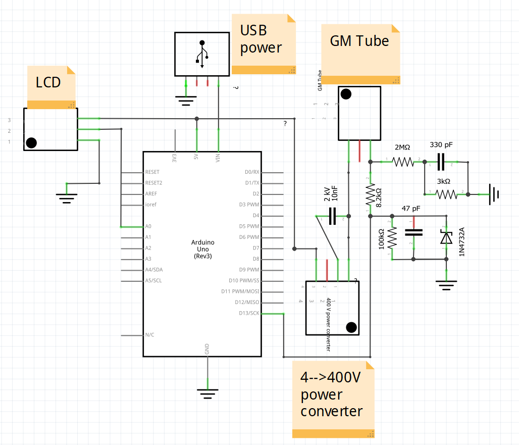
The construction is very straight forward (refer to circuit diagram). The only difficult aspects of this project was obtaining some of the parts (the GM tube and the high voltage converter). I purchased both of these items for little money on Ebay, but both were being sold from far away (the Ukraine and China respectively) so it took 3-4 weeks to receive the items.
I started with assembling the circuit on a bread board to best evaluate the circuit and where I could manipulate it to my desires. I assembled it per AdNovea's diagram, but left out the buzzer, ethernet module, and resistor leading to the GM tube (I was not getting sufficient current to the tube with that circuit design that prevented it from working). I then soldered it all onto a circuit board.
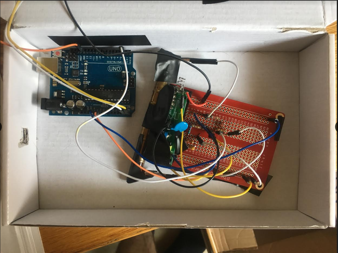
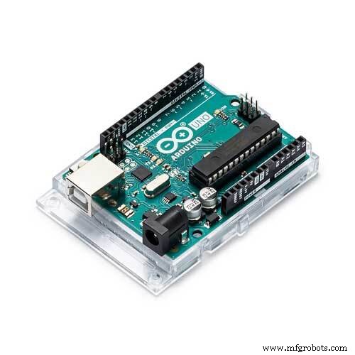
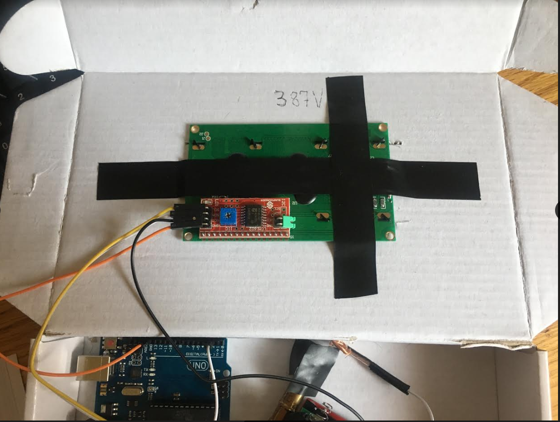
I have an Arduino uno cited here as what I used, but you could probably save space in a container by using a nano. I used electrical tape to attach the GM tube to the circuit board to save space as well as to cover the terminals on the voltage transformer to improve safety. As I have limited equipment to play around and drill holes with a plastic container to make something pretty like what AdNovea had, I used the cardboard box that I was given when I first purchased my Arduino circuit kit.
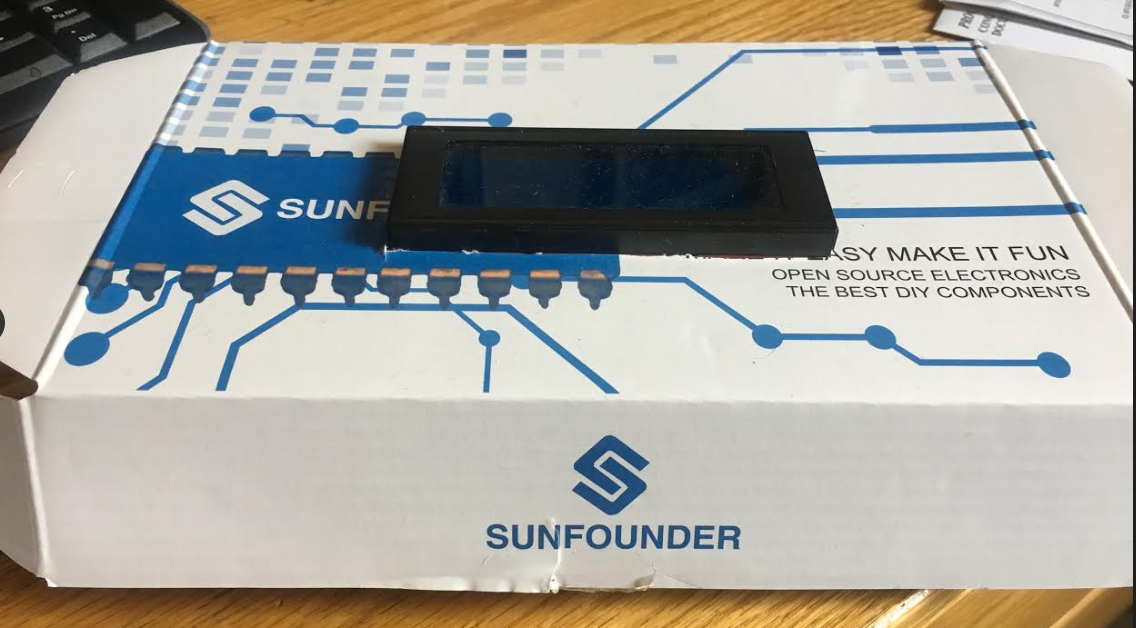
I did cut a hole in the top of the box so the LED display could fit snugly in there (and I further reinforced this with tape).
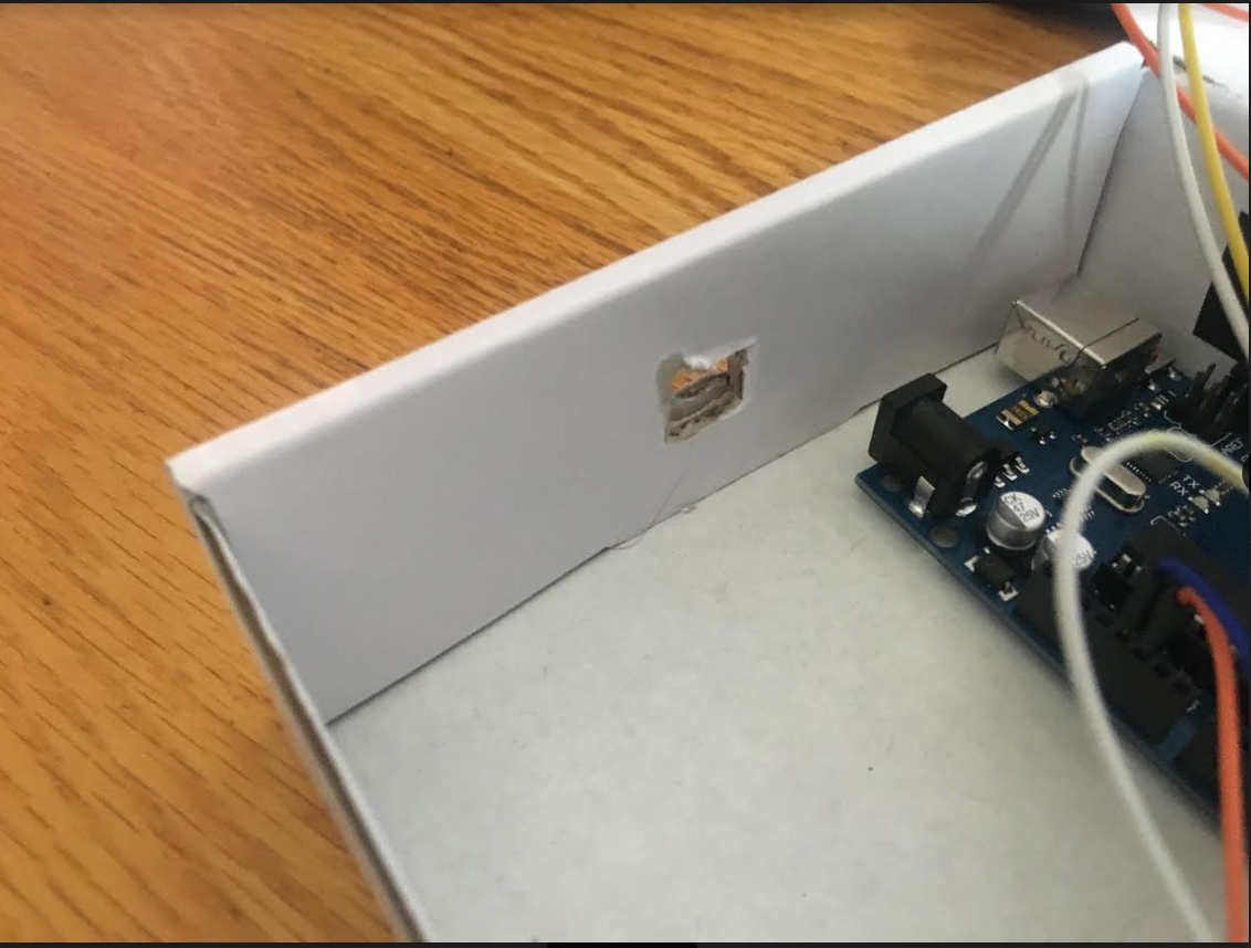
I also cut a hole in the side of the box to permit a USB cord to come in and power the device.
I attempted 9V batteries to start, but as expected, the batteries did not last long. Finally I put additional electric tape around the box/circuit board as needed at points where the circuit may come in contact with the cardboard to protect against fire and losing signal.
The program I have designed for my project takes the counts collected by the GM tube every 30 seconds multiplied by 2 to provide an estimated counts per minute (measuring unit of GM tubes). I then used metric system conversions to report uSv/hr that is a more widely used reference measurement. As the device continues to run through this code, I had it report the average of the measurements that progressively were collected along with the standard error (SD / sqrt(n)). Statistically I chose standard error as ultimately what is collected is a sample from the mean background radiation levels making SE the more appropriate measure. Unfortunately due to the memory limitations of the Arduino, I was only able to create an array of measurements of 100 items (if I played around with it more, perhaps more than this). Thus the tube will only accurately display values for 50 minutes, which is a good sample size none-the-less.
As I wanted to move to my next project (building a vein-finder type device as I am a medical professional), I did not go after some smaller changes I could make for the device (placing buzzer so if CPM is over background radiation it would sound an alarm with warning text, play around with my 'log period' variable to formally evaluate accuracy with shorter periods to provide more rapid measurements that are reasonable), but others who want to work on this device a bit more should completely play around with this as much as they want and make it better.
Code
- Code
CodeArduino
#include <LiquidCrystal_I2C.h>
#include <Wire.h>

unsigned long counts; //variable for GM Tube events
unsigned long previousMillis; //variable for measuring time
float averageCPM;
float sdCPM;
int currentCPM;
float calcCPM;
LiquidCrystal_I2C lcd(0x27, 20, 4);
float CPMArray[100];

#define LOG_PERIOD 30000 // count rate (in milliseconds)

void setup() { //setup
  counts = 0;
  currentCPM = 0;
  averageCPM = 0;
  sdCPM = 0;
  calcCPM = 0;
  lcd.init();
  lcd.backlight();
  Serial.begin(9600);
  pinMode(2, INPUT);
  attachInterrupt(digitalPinToInterrupt(2), impulse, FALLING); //define external interrupts
}

void loop() { //main cycle
  lcd.setCursor(0,2);
  lcd.print("CPM Count: ");
  lcd.print(counts);
  unsigned long currentMillis = millis();
  if (currentMillis - previousMillis > LOG_PERIOD) {
    previousMillis = currentMillis;
    CPMArray[currentCPM] = counts * 2;
    lcd.clear();
    lcd.setCursor(0,0);
    lcd.print("uSv/hr: ");
    lcd.print(outputSieverts(CPMArray[currentCPM]));
    counts = 0;
    averageCPM = 0;
    sdCPM = 0;
    //calc avg and sd
    for (int x=0;x<currentCPM+1;x++)  {
      averageCPM = averageCPM + CPMArray[x];
    }
    averageCPM = averageCPM / (currentCPM + 1);
    for (int x=0;x<currentCPM+1;x++)  {
      sdCPM = sdCPM + sq(CPMArray[x] - averageCPM);
    }
    sdCPM = sqrt(sdCPM / currentCPM) / sqrt(currentCPM+1);

    Serial.println("Avg: " + String(averageCPM) + " +/- " + String(sdCPM) + "  ArrayVal: " + String(CPMArray[currentCPM]));
    currentCPM = currentCPM + 1;
    displayAverageCPM();
  }
}

void impulse() {
  counts++;
}
void displayAverageCPM()  {
  lcd.setCursor(0,1);
  lcd.print("Avg: ");
  lcd.print(outputSieverts(averageCPM));
  lcd.print("+/-");
  lcd.print(outputSieverts(sdCPM));
}
float outputSieverts(float x)  {
  float y = x * 0.0057;
  return y;
}
Schematics
Schematic is weird so when you open with Fritzing, things are moved around for some reason.geiger_counter_4LAnJvZEpC.fzzManufacturing process
- Build a Raspberry Pi Geiger Counter – Open‑Hardware Radiation Sensor Tutorial
- Real-Time Solar Panel Monitoring with Arduino: Low-Cost Data Acquisition System
- Build a Bluetooth‑controlled Arduino Spybot
- Ensure Safe Hot Water Heating: Thermocouple Voltage Monitor for Pilot Lights
- Create a Custom Punchable Keyboard Button with Arduino: A Step-by-Step Guide
- Smart Parking Counter: Real‑Time Vehicle Tracking with Arduino, Processing, and PHP
- High‑Speed Arduino RPM Counter Using a Novel Algorithm
- Build a Handheld Geiger Counter Using Arduino Nano
- Valentine's Day Gift: DIY Days‑Together Counter
- Arduino Relay Tutorial: Safely Control High‑Voltage Devices