


ED BMSdiag – Arduino CAN‑BUS & OBD‑II Diagnostic Kit
Components and supplies
 |
| × | 1 | |||
 |
| × | 1 | |||
 |
| × | 1 | |||
| × | 1 | ||||
| × | 1 | ||||
| × | 1 | ||||
| × | 1 |
Apps and online services
 |
|
About this project
I am driving an electric car - a smart for two electric drive. The health of the traction battery is essential and is maintained by a battery management system (BMS). It will monitor all 93 cells during charge / discharge and cares about an equally voltage level balance. Normally only service tools can read information from this ECU.
The car is equipped with a GSM modem for accessing status data like state of charge (SOC), the available range and other simple information. For a certain time the modem was in extended mode gathering diagnostic information about the car. Curious about the content I tried to sniff into the CAN bus to know what was transmitted.
Inspired by similar projects for other electric cars - like the Nissan Leaf - I recorded the complete CAN bus traffic while driving or while charging the car. First sniffed streams really included those diagnostic data - but how to decode it?
You will find details about the CAN bus sniffing and reverse engineering in a separate article here.
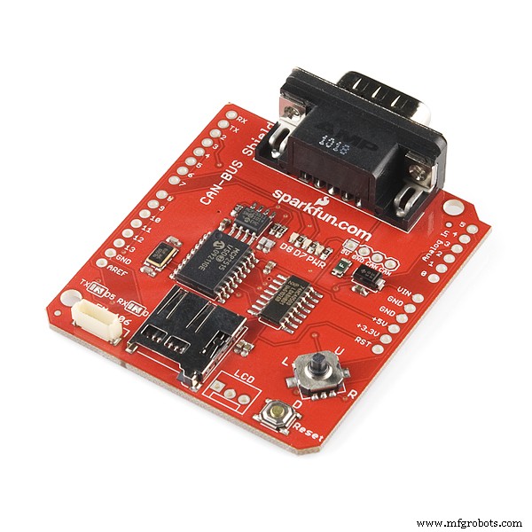
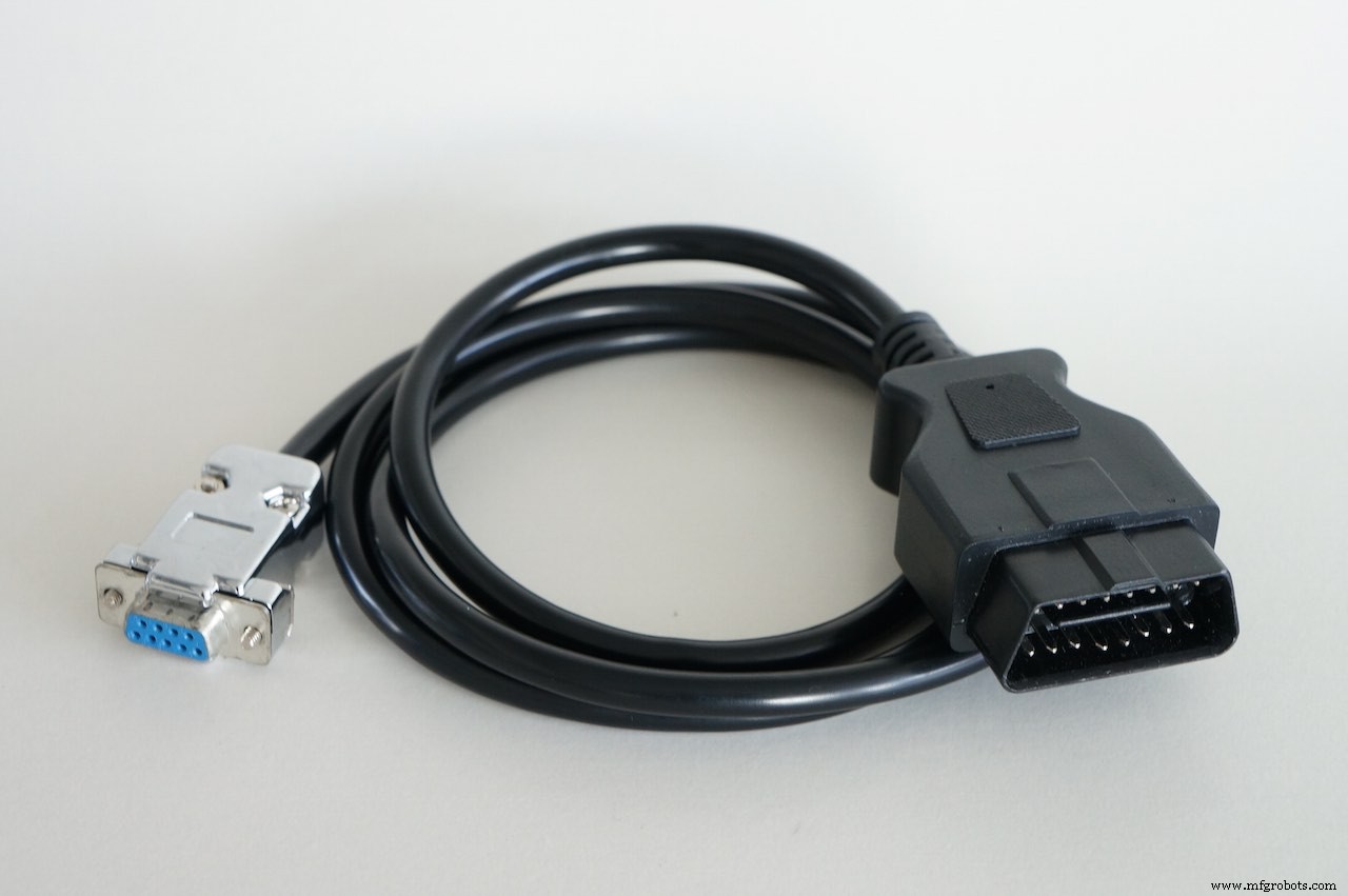
What is NeededGet the required hardware. On modern cars the physical layer is done via CAN bus. At least two CAN bus shields are available - see component list. You have to connect to the cars diagnostic port - the OBD-connector, so buy a cable or make your own. NOTE: there are two standards for OBD to DSUB-9 cables - pick the right one! See pictures below:
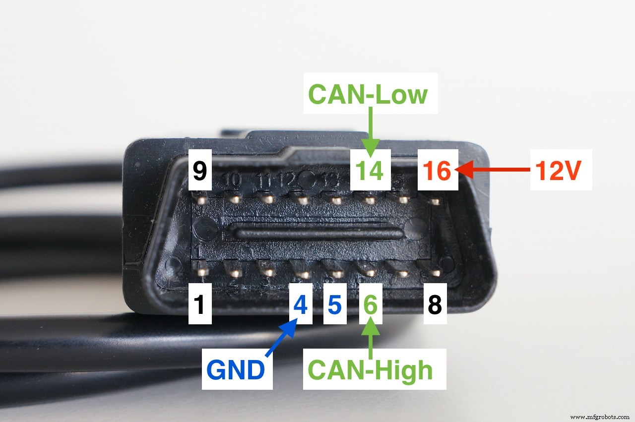
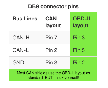
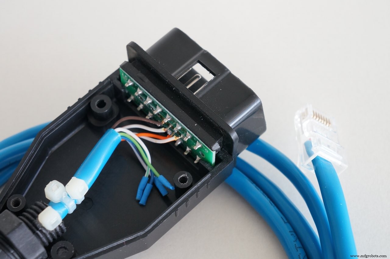
When you make your own cable, it is a good idea to use an old twisted pair networking cable. Use one of those paired wires for CAN-H and CAN-L. This will improve signal integrity. Also DO NOT exceed 1 m in length, to minimize signal reflections.
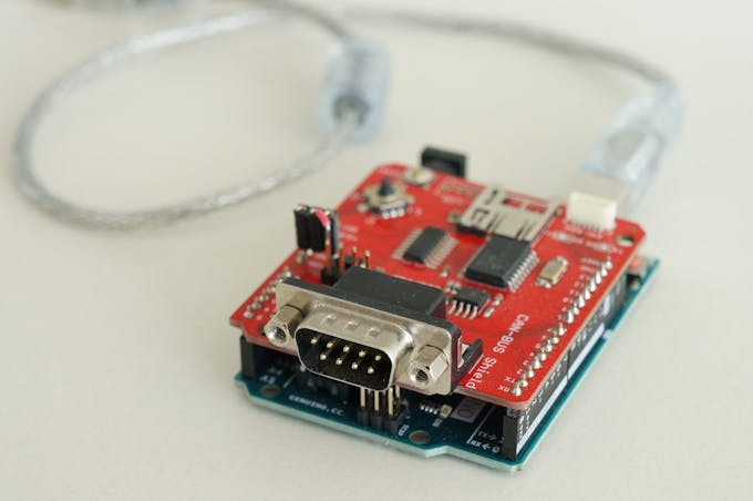
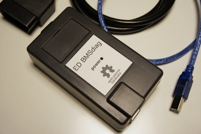
Get StartedStep 1
Prepare the hardware and find a nice case for the boards.
Step 2
Download the project from my github repository. See details there for installation. Compile the code and flash it to the Arduino.
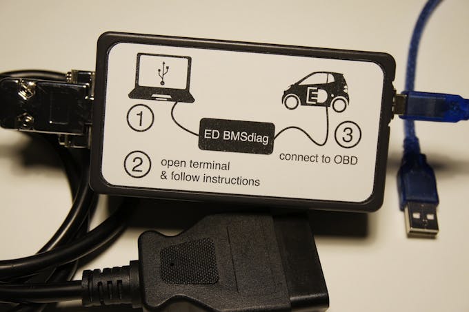
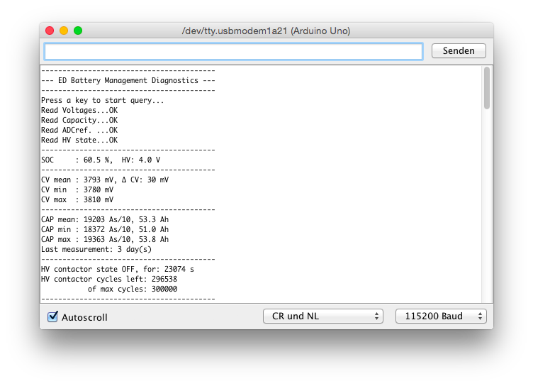
Step 3
Connect to the car and power it up. Start the diagnostics session and get useful info about your battery pack...
Step 4
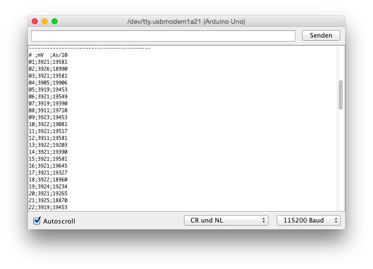
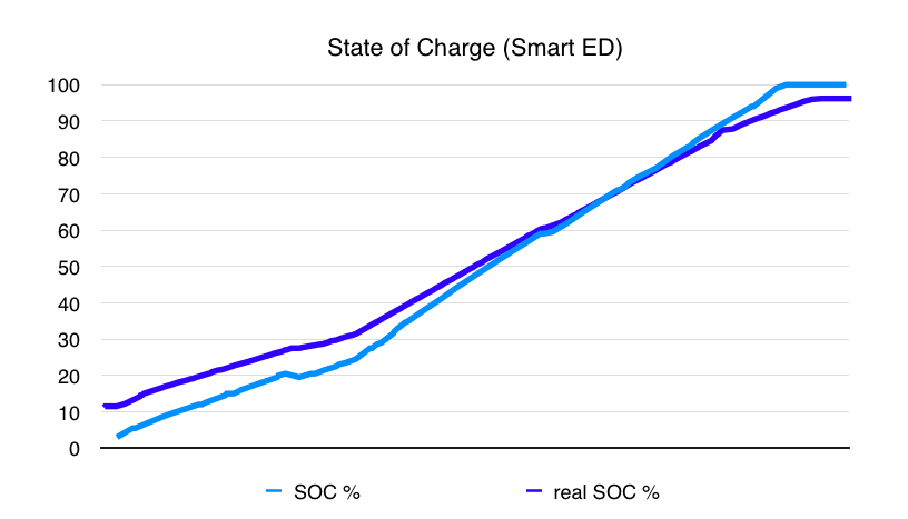
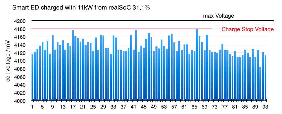
Use a spreadsheet program and find out correlating data. For example compare the SOC (State of Charge, from the dashboard) with the real SOC from the BMS. Or plot the cell-voltages and see that some cells are limiting the pack while charging, because they reach the cut-off limit at first...
Step 5
Improve the code if you want - do your own hacking. The Spakfun shield has a SD-card reader, so you could build your own CAN bus logger.
Or you build a nice frontend / app displaying the data...
I hope this tool will be helpful - Have fun!
Code
ED_BMSdiag Arduino Software
https://github.com/MyLab-odyssey/ED_BMSdiag.gitSchematics
for Sparkfun CAN-Bus shield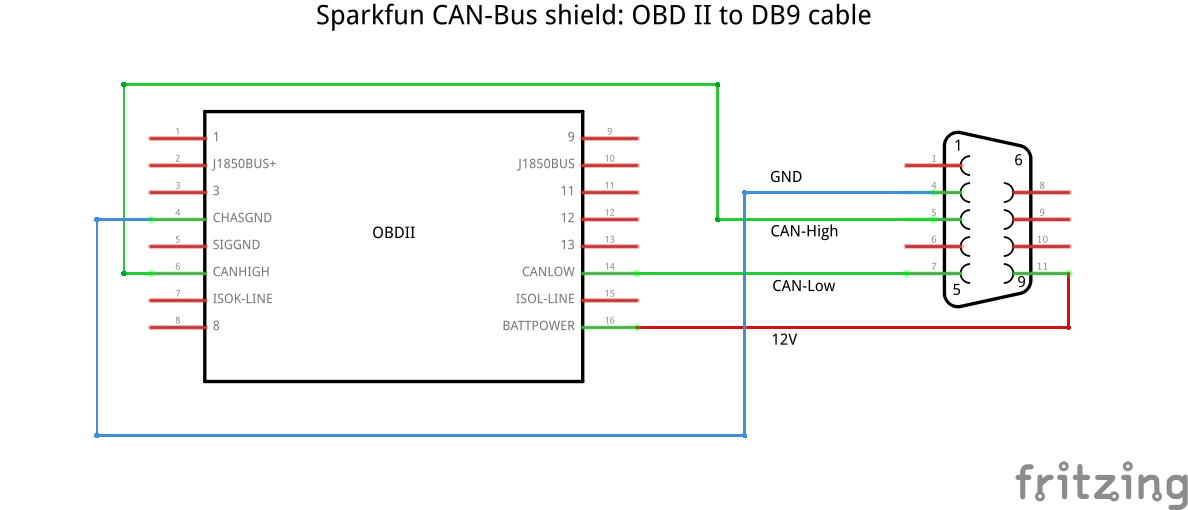 for CANdiy-shield
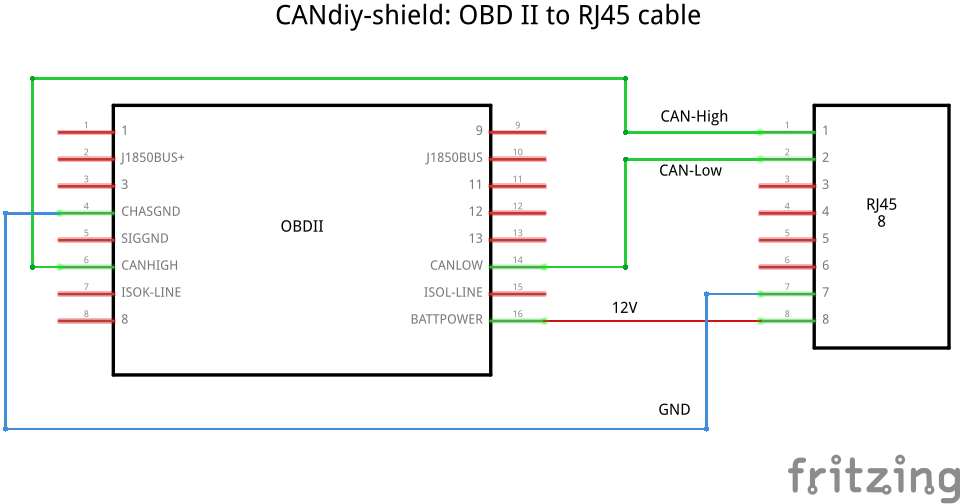
Manufacturing process
- Web‑Controlled DMX Lighting System – Arduino Master Controller
- Build a Bluetooth‑controlled Arduino Spybot
- Wireless Arduino Programming Shield with HC-05 Bluetooth – No USB Needed
- High-Performance 2.8” TFT Shield for Arduino Nano – 320×240 SPI Display
- Arduino-Driven GrowBox Controller – Open-Source Firmware & Hardware Guide
- Smart Domotic Greenhouse: Automated Climate Control with Arduino
- J.A.R.V.I.S. – Smart Home Virtual Assistant Powered by Arduino
- Arduino UNO Web-Enabled Servo Control with PHPoC WiFi Shield
- Smart Herb Box Eco System: Alexa‑Enabled Indoor Gardening Kit
- Master Arduino Shields: Complete Guide to Adding Functionality