


Arduino Nano 33 BLE Sound Spectrum Visualizer: Real-Time Audio Display
Components and supplies
 |
| × | 1 | |||
| × | 1 | ||||
| × | 1 | ||||
| × | 1 | ||||
 |
| × | 1 | |||
| × | 1 |
Apps and online services
 |
|
About this project
IntroductionSee how a bar graph respond to music and sound in a little OLED display. Lowest frequencies toward the left end of the graph, highest frequencies toward the right.
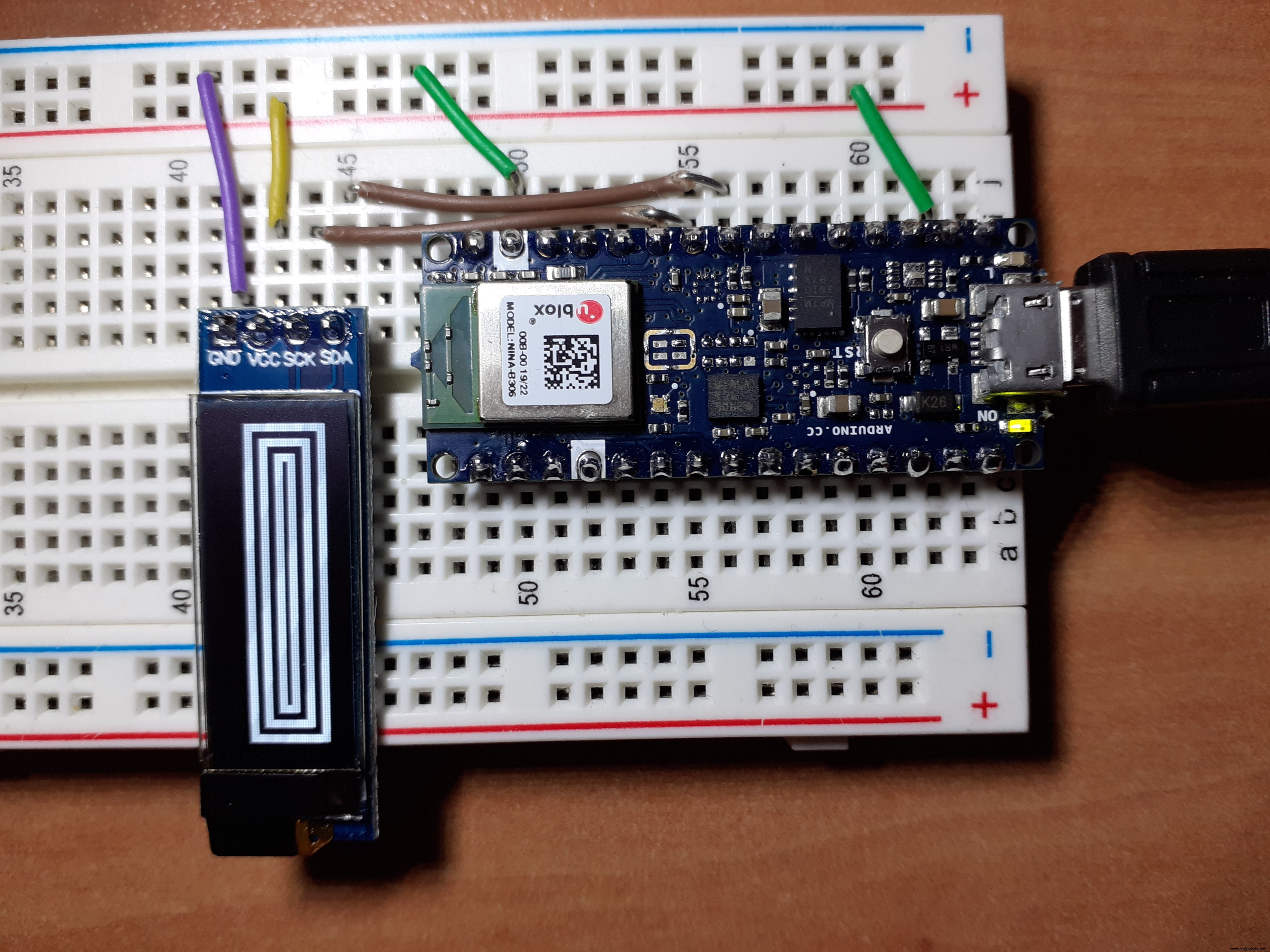
Construction
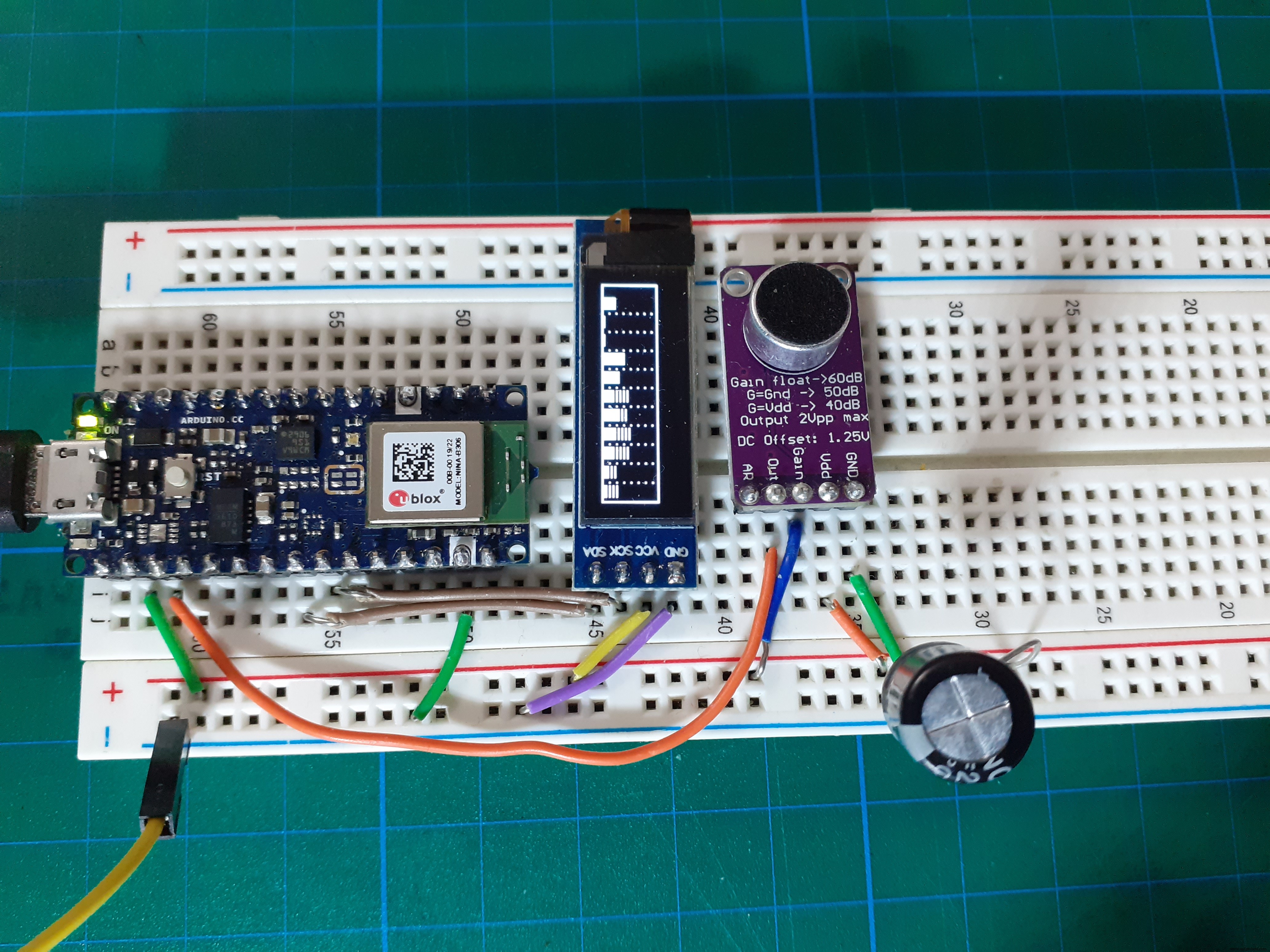
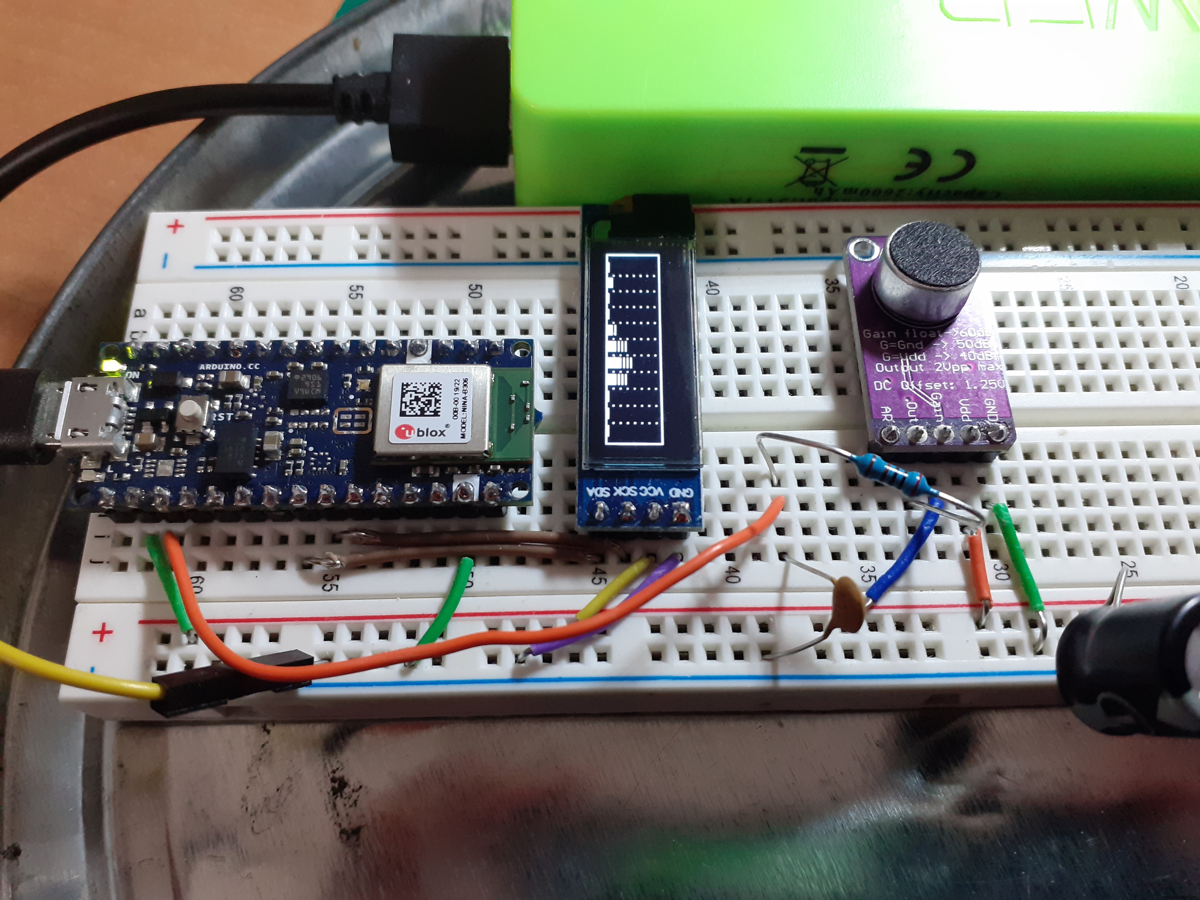
Connections
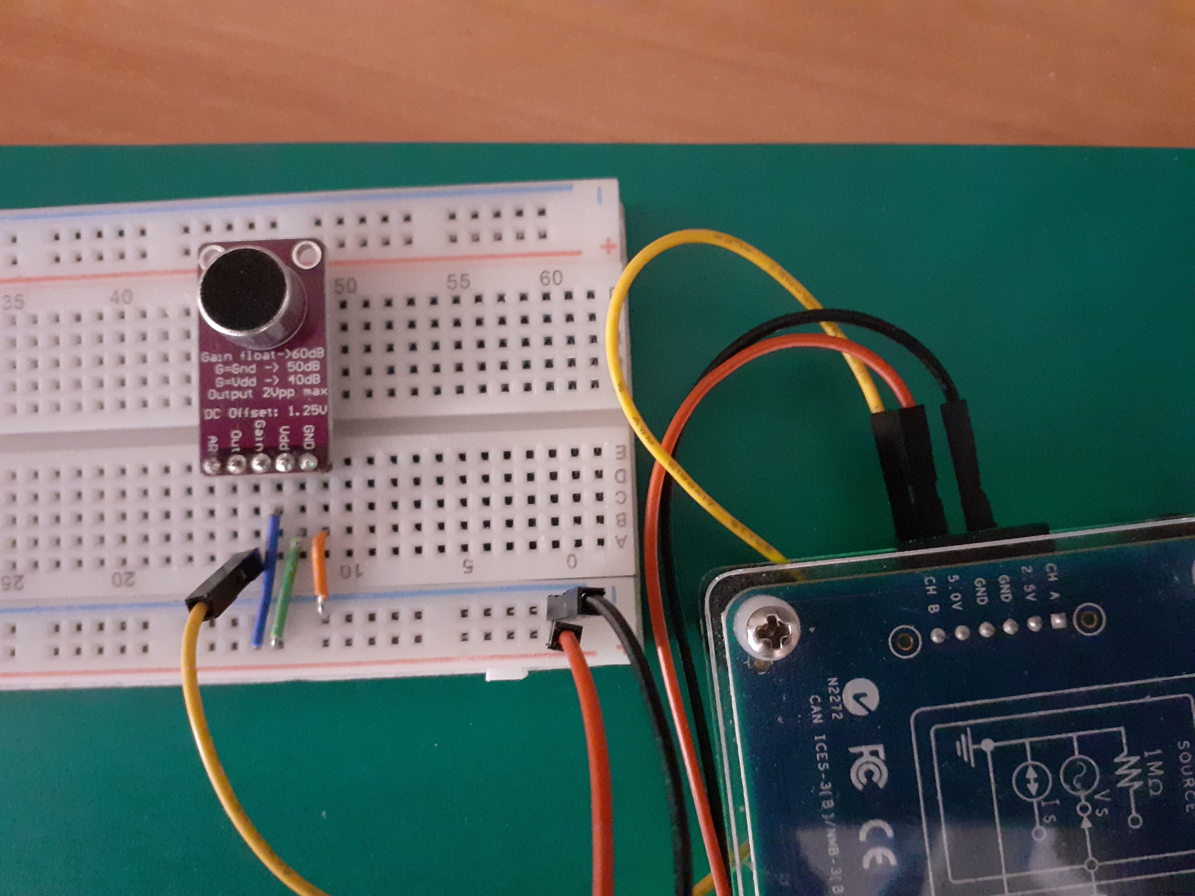
- Connect Mic GAIN depending the sensibility that better suits your system: VCC to mic GAIN for 40dB, low sensitivity, GND to mic GAIN for 50dB, medium sensitivity or let floating the mic GAIN for 60dB, high sensitivity.
- Connect Analog pin 0 A0 to mic amp OUT
- Connect 3.3V, GND, SDA (or analog 4 A4) and SCL (analog 5 A5) to I2C SSD1306
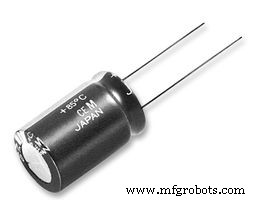
- connect a 470 uF capacitor between VCC and GND in power bus
Getting low frequency noise?
The noise comes from any electric devices near your measuring system that are working. All of the electronic devices work with a fixed frequency and voltage of alternative current (AC) with the frequency of 50 Hz or 60 Hz is the power line frequency in your country. You can use a faraday cage to eliminate the noise easily. Put your circuit inside a box and connect the box to ground. Ground well the circuit.
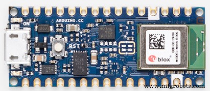
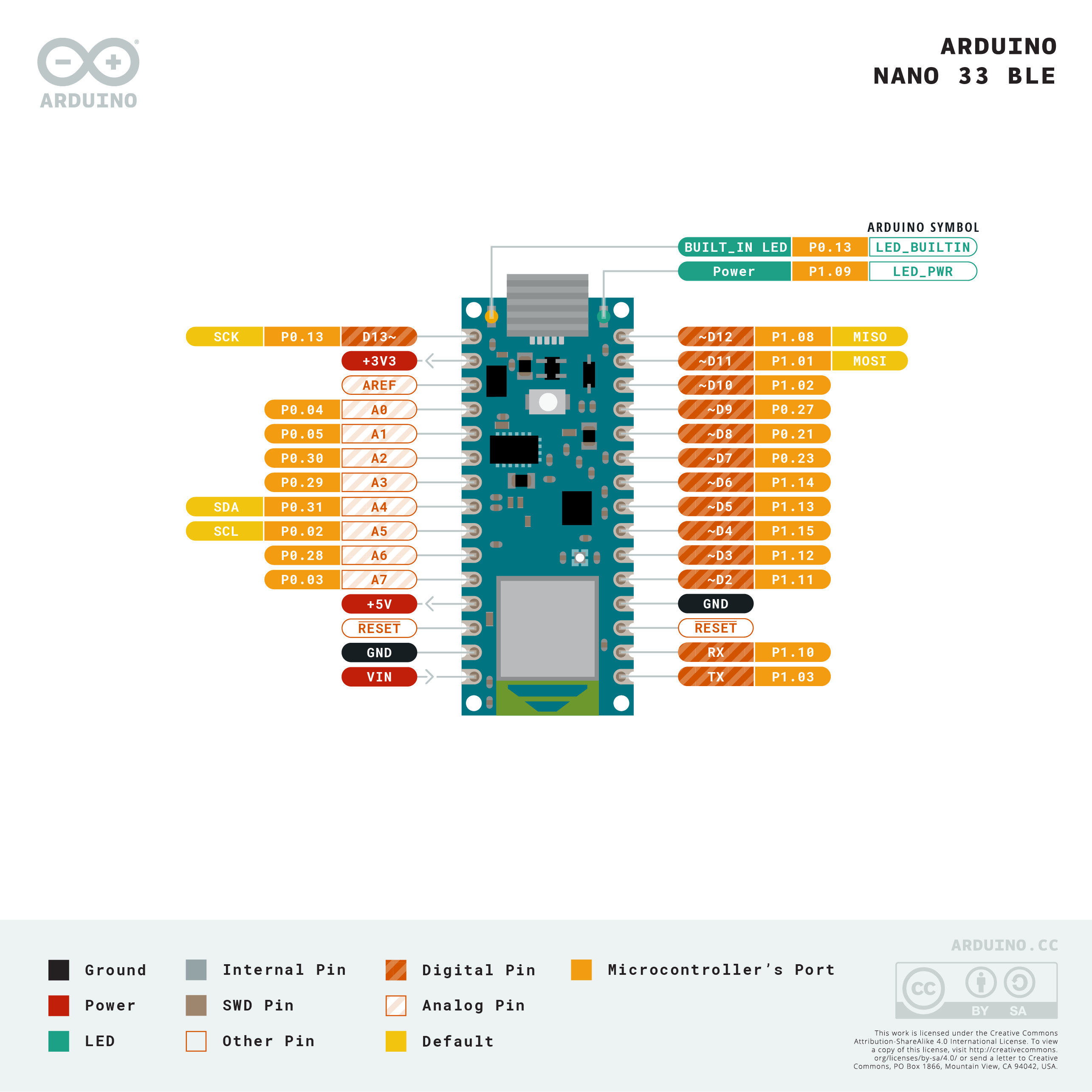
Pinout of Arduino Nano 33 BLE
Using arduino core AnalogRead and the Arduino Nano 33 BLE we can only get about 35, 000 samples per second so we cannot use FFT for frequencies above 17.5 Khz, as we have to read the clock and make several comparisons in a busy waiting loop we are going to be cautious and take an upper limit of 8 kHz . So we can use a simple RC low pass filter to avoid annoying solutions beyond that frequency.
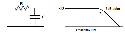
R = 180Ω C = 0.1uF for a Cut-off frequency fc = 8842 [Hz]
Here using a 2K Ohm resistor and a 4.7 nF capacitor for a Cut-off frequency fc = 17000[Hz]
Using the normal Arduino analogRead() function is too slow for sampling audio, so let's calculate the maximum sample rate.
We are going to estimate how many samples we can get using arduino core AnalogRead and the Arduino Nano 33 BLE.
Let's run this little program to have an estimate.
/*
 * Rough calculation of maximum sample rate with AnalogRead
 */

#define ANALOG_PIN A0

#define SAMPLES 1000000.0
int newTime;
int analogValue;
void setup() {

  Serial.begin(9600);
  Serial.println("Sampling... please, wait. ");
}

void loop() {
  // put your main code here, to run repeatedly:
  newTime = micros();

  // 1 millon samples
  for (int i = 0; i < (int)SAMPLES; i++){
    analogValue = analogRead(ANALOG_PIN);
  }
  float elapsedTimePerSampleUs = (micros()- newTime) / SAMPLES;
  Serial.print("Time per sample (us): ");
  Serial.println(elapsedTimePerSampleUs);
  Serial.print("Max sampling freq(hz): ");
  Serial.println(pow(10,6) /elapsedTimePerSampleUs );
}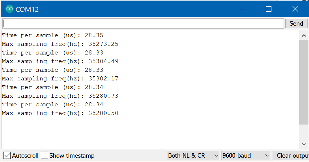
Using arduino core AnalogRead and the Arduino Nano 33 BLE we can only get about 35, 000 samples per second. The approximately double-rate requirement, consequence of the Nyquist theorem will limit our spectrum visualizer to frequencies below 17 kHz. We can use a low pass filter to skip frequencies above that limit.
We have to read the clock and make several comparisons in a busy wait loop, we are going to be cautious and take an upper limit of 8 kHz.
// take samples
  for (int i = 0; i < SAMPLES; i++) {
    unsigned long newTime = micros();
    int value = analogRead(ANALOG_PIN);
    vReal[i] = value;
    vImag[i] = 0;
    while (micros() < (newTime + sampling_period_us)) {
      yield();
    }
  }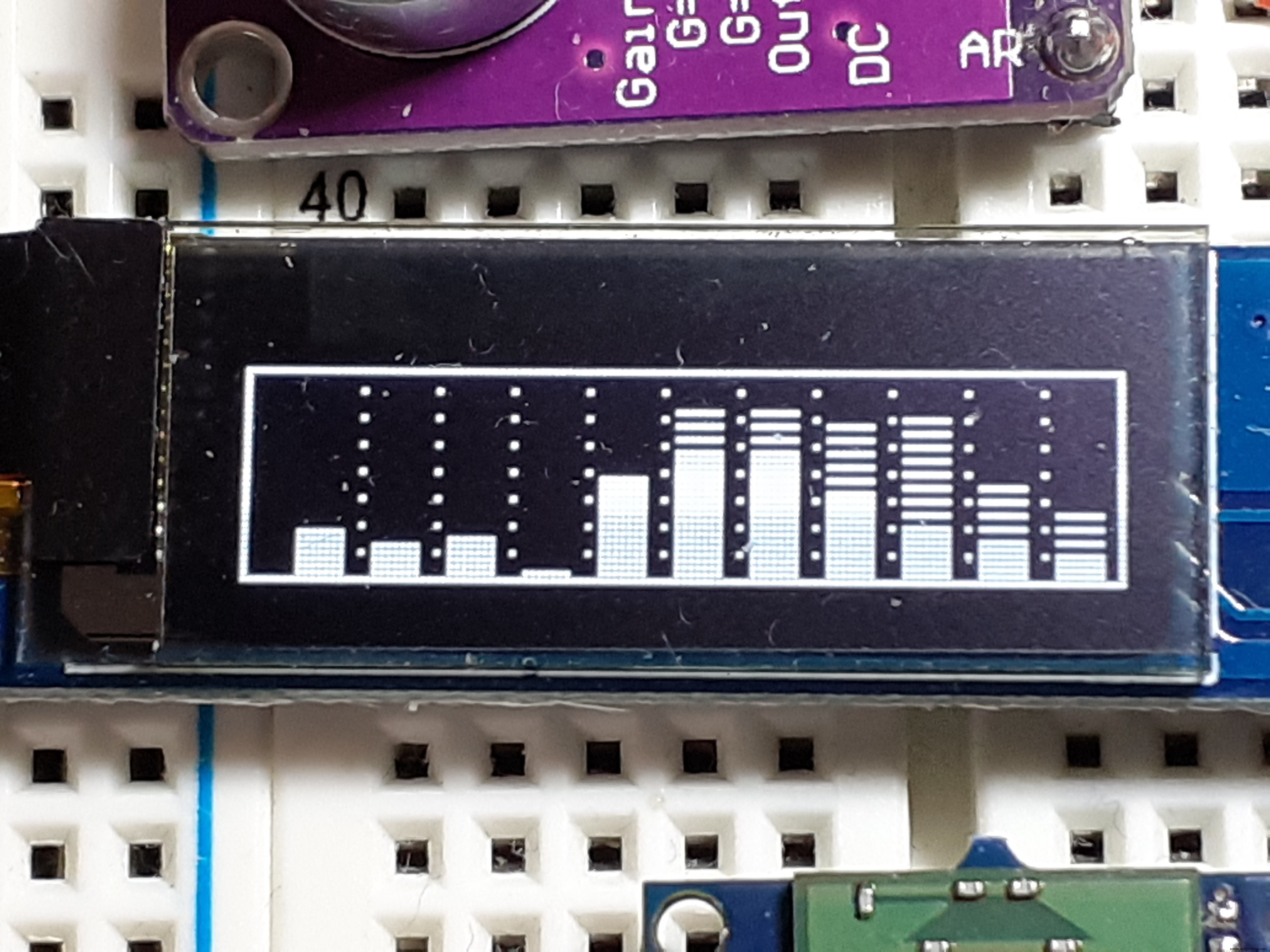
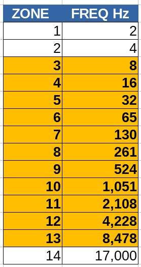
The screen is divided in eleven frequency zones and you a logarithmic scale grouping frequencies similar to how the human ear perceives them.
Humans can detect sounds in a frequency range from about 20 Hz to 20 kHz. (Human infants can actually hear frequencies slightly higher than 20 kHz, but lose some high-frequency sensitivity as they mature; the upper limit in average adults is often closer to 15–17 kHz.)
Will use zones 3 to 13 (11 zones) for our representation.
Each bar represents the maximum value in the band with spaced lines and the mean value in the band with a filled rectangle.
Values are shown using decibels with a preselected reference obtained in a heuristic way.
How it works?The audio samples are converted into a frequency spectrum using a fast Fourier transform or FFT.
Then the spectrum is divided and grouped in 14 zones and only 11 zones are represented in dB.
About the microphone module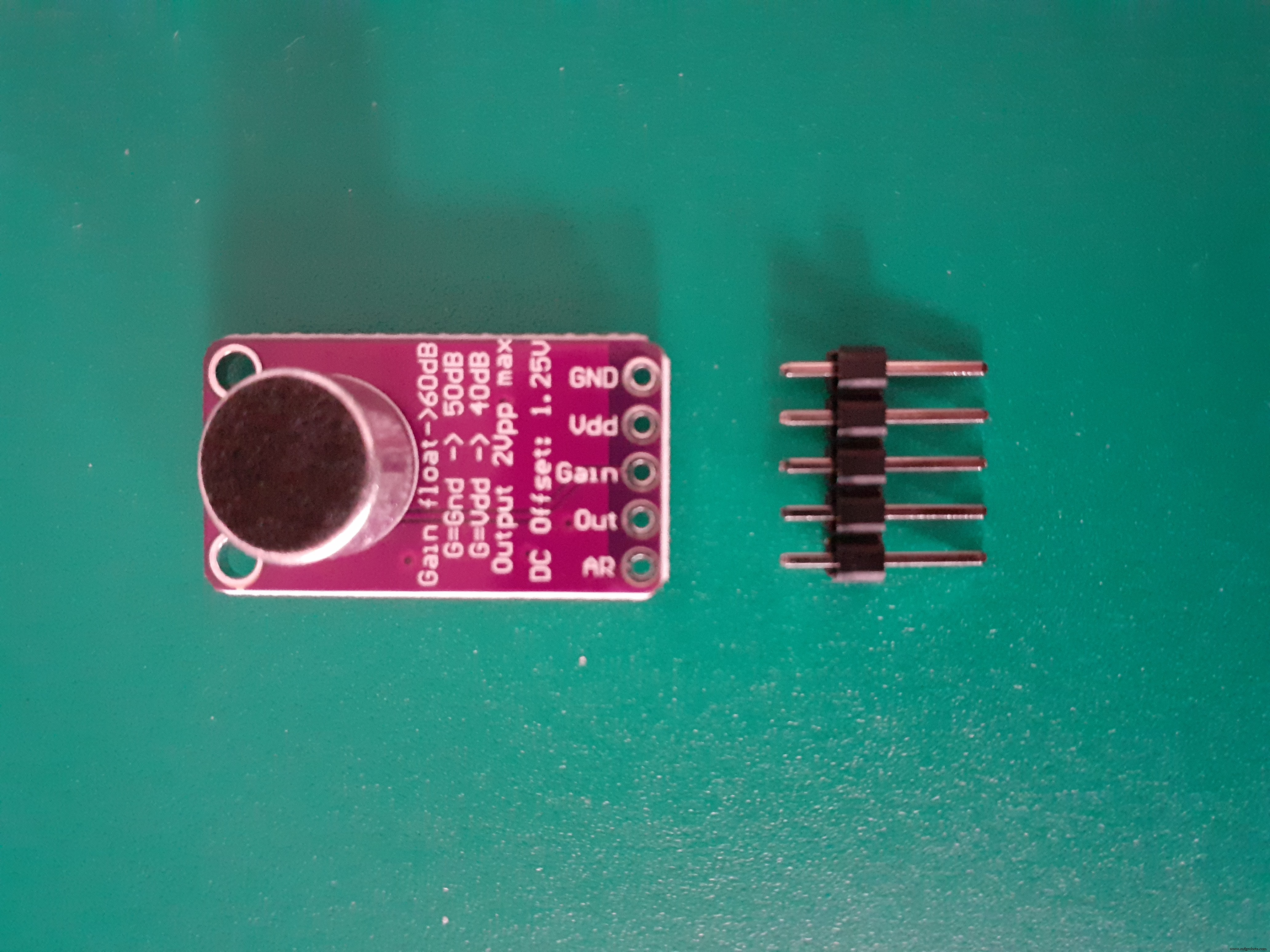
Electret Microphone
Electret is a quasi-permanently charged dielectric. It is made by heating a ceramic material, placing it in a magnetic field then allowing it to cool while still in the magnetic field. It is the electrostatic equivalent of a permanent magnet. In an electret microphone a slice of this material is used as a part of the dielectric of a capacitor in which the diaphragm of the microphone forms one plate. Sound pressure moves the diaphragm. The movement of the plate varies the capacitance according to the sound pressure. Given the built-in fixed charge of the dielectric, the voltage across the capacitor will also vary. The electret capacitor is connected to the input of a built in FET amplifier. Electret microphones are small, have excellent sensitivity, a wide frequency response and generally a very low cost.
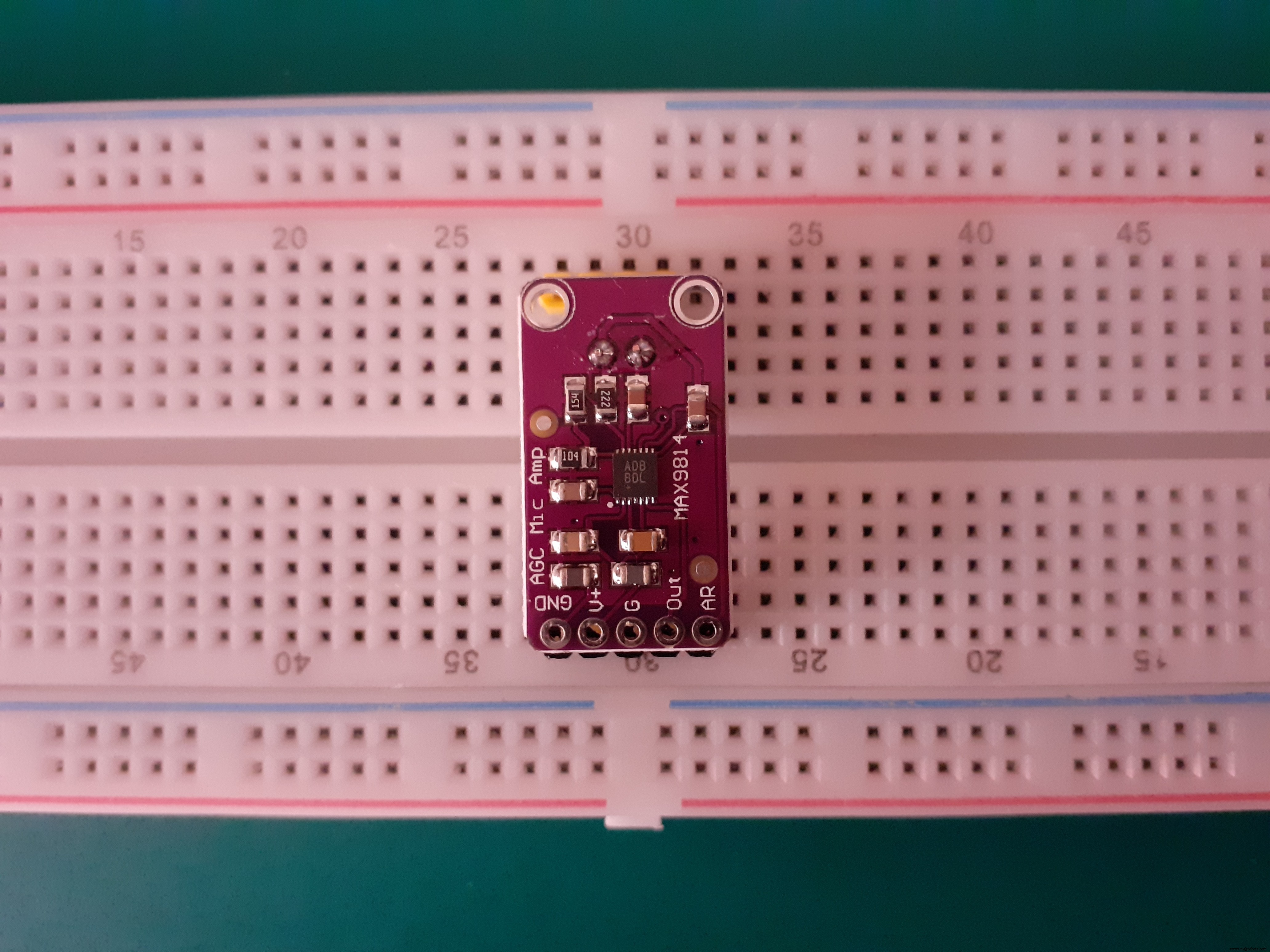
MAX9814 Microphone Amplifier
The MAX9814 is a microphone amplifier with automatic gain control (AGC) and low noise microphone bias and and has a few options you can configure with the breakout.
The MAX9814 module has three amplifier settings (40dB, 50dB, 60dB). The default is 60dB, but can be set to 40dB or 50dB by jumpering the Gain pin to VCC or ground.
Internal low-noise microphone bias 1.25V, 2Vpp. The ouput from the amp is about 2Vpp max on a 1.25V DC bias, so it can be easily used with any Analog/Digital converter that is up to 3.3V input.
The Attack/Release ratio also can be modified, from the default 1:4000 to 1:2000 or 1:500.
For connecting directly to a Line Input, you need a blocking capacitor / coupling capacitor to block the DC component. You can use a blocking capacitor in series above 1uF, depends on your system, if in doubt try from 33 uF to 100uF. A coupling circuit allows AC signals to flow from one part to another while blocking the DC components. In audio circuits, this is done to prevent DC components from distorting the audio output. The effectiveness of a coupling capacitor depends on a broad array of frequency-dependent parameters including insertion loss, equivalent series resistance and series resonant frequency.
Power supply: 2.7V to 5.5V
Sensitivity
Sensitivity, the ratio of the analog output voltage or digital output value to the input pressure, is a key specification of any microphone. Mapping units in the acoustic domain to units in the electrical domain determines the magnitude of the microphone output signal, given a known input.
The sensitivity of a microphone is the electrical response at its output to a given standard acoustic input. The standard reference input signal for microphone sensitivity measurements is a 1 kHz sine wave at 94 dB sound pressure level (SPL), or 1 pascal (Pa, a measurement of pressure). A microphone with a higher sensitivity value has a higher level output for a fixed acoustic input than a microphone with a lower sensitivity value. Microphone sensitivity in decibels (dB) is typically a negative number; therefore, a higher sensitivity is a smaller absolute value.
For analog microphones, the sensitivity is typically specified in units of dBV, that is, decibels with reference to 1.0 V rms.
Reference level and Frequency Response
The frequency response of a microphone describes its output level across the frequency spectrum. The high and low frequency limits are described as the points at which the microphone response is 3 dB below the reference output level at 1 kHz. The reference level at 1 kHz is customarily normalized to 0 dB.
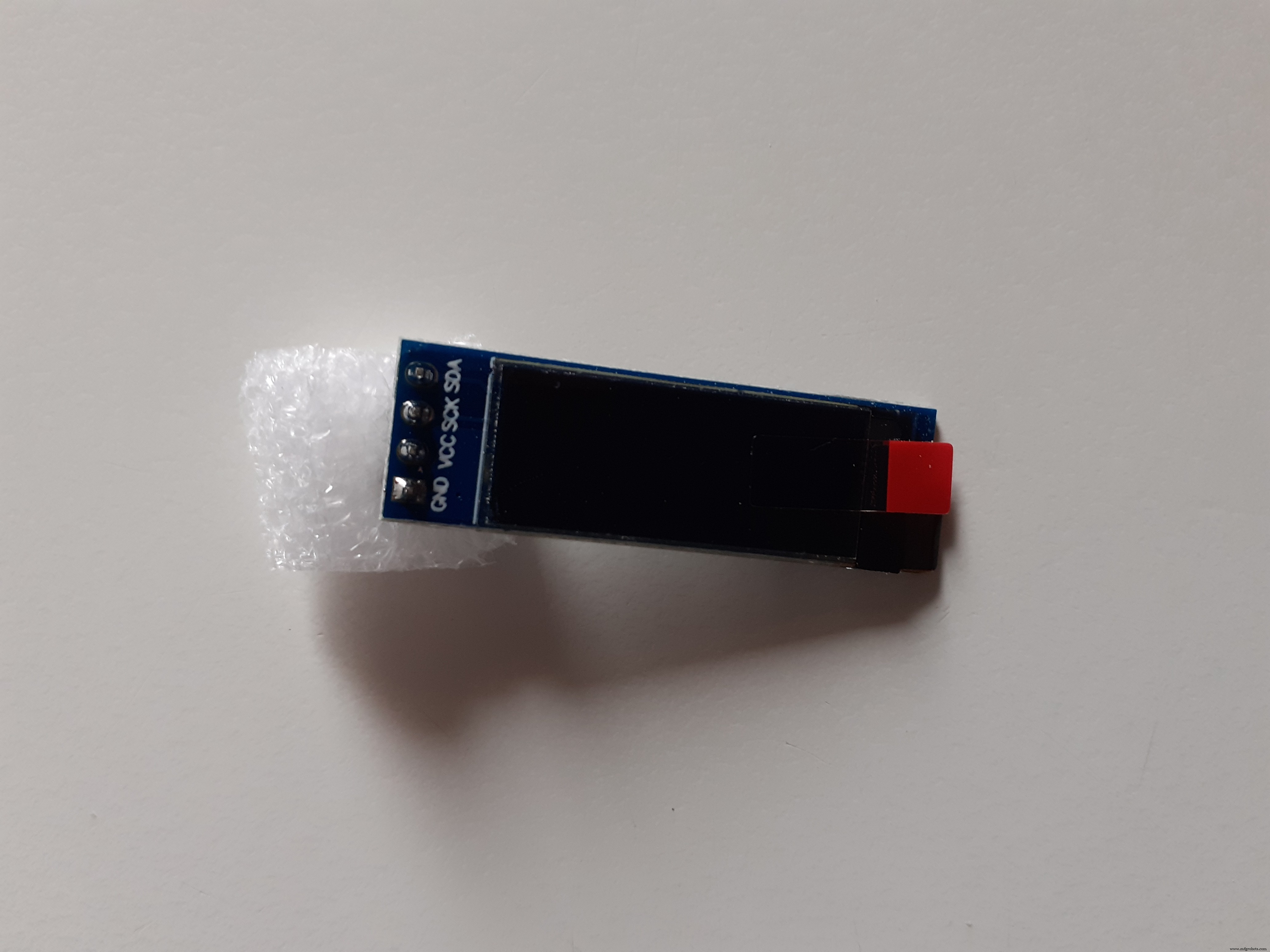
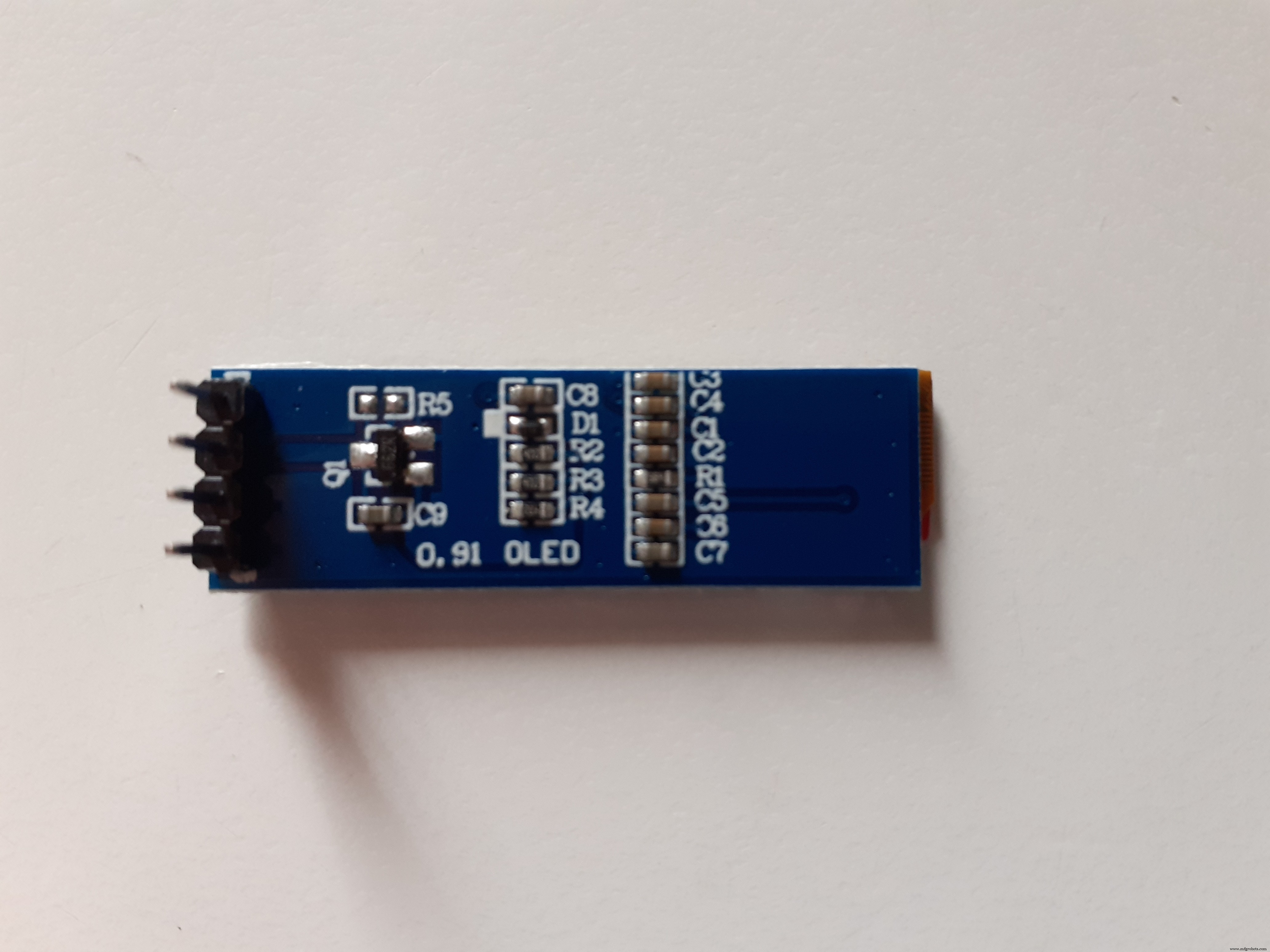
0.91 inch OLED I2C Display 128 x 32 PixelsThis is a small display, only about 1" diagonal. It is made of 128x32 individual white OLED pixels, each one is turned on or off by the controller chip. No backlight is required. This reduces the power required to run the OLED.
The model we’re using here has only four pins and communicates with the Arduino using I2C communication protocol. This model has no RESET pin. You just need to connect to the Arduino Uno I2C pins:
- Arduino Nano: SDA (A4); SCL (A5);
To control the OLED display you need the adafruit_SSD1306.h and the adafruit_GFX.h libraries. Follow the next instructions to install those libraries.
We are using Adafruit libraries. Remember you can buy something from Adafruit to support them.
Next steps
Arduino Nano 33 BLE uses a can do be better getting analogs reads. Next version I will use FFT and Analog input optimized for the nrf52840.
Code
- Sound Spectrum Visualizer for Arduino Nano 33 BLE
Sound Spectrum Visualizer for Arduino Nano 33 BLEArduino
Sound Spectrum Visualizer for Arduino Nano 33 BLEuses arduinoFFT https://github.com/kosme/arduinoFFT
uses Adafruit_GFX https://github.com/adafruit/Adafruit-GFX-Library
uses Adafruit_SSD1306 https://github.com/adafruit/Adafruit_SSD1306
/*

  Sound Spectrum Visualizer for Arduino Nano 33 BLE
  Arduino based sound visualizer
  @author Enrique Albertos

  Hardware requirements:
   - Arduino or Arduino-compatible boards.
   - ssd1306 oled I2C 128x32 display
   - Electret Microphone Amplifier with max9814
   - Optional: battery for portable use (else power through USB)

  Software requirements:
  - arduinoFFT https://github.com/kosme/arduinoFFT
  - Adafruit_GFX https://github.com/adafruit/Adafruit-GFX-Library
  - Adafruit_SSD1306 https://github.com/adafruit/Adafruit_SSD1306

  Connections:
  - Mic GAIN:
       * VCC to mic GAIN for 40dB
       * GND to mic GAIN for 50dB
       * floating mic GAIN for 60dB
  - Analog pin 0 to mic amp output
  - +3.3V, GND, SDA (or analog 4) and SCL (analog 5) to I2C SSD1306

  @uses arduinoFFT https://github.com/kosme/arduinoFFT
  @uses Adafruit_GFX https://github.com/adafruit/Adafruit-GFX-Library
  @uses Adafruit_SSD1306 https://github.com/adafruit/Adafruit_SSD1306

  This program is free software: you can redistribute it and/or modify
  it under the terms of the GNU General Public License as published by
  the Free Software Foundation, either version 3 of the License, or
  (at your option) any later version.

  This program is distributed in the hope that it will be useful,
  but WITHOUT ANY WARRANTY; without even the implied warranty of
  MERCHANTABILITY or FITNESS FOR A PARTICULAR PURPOSE.  See the
  GNU General Public License for more details.


*/

#include "arduinoFFT.h"

#include <Adafruit_GFX.h>
#include <Adafruit_SSD1306.h>
#define SAMPLES 1024 // power of 2
#define SAMPLING_FREQ 24000 // 12 kHz Fmax = sampleF /2
#define AMPLITUDE 100 // sensitivity
#define FREQUENCY_BANDS 14


#define SCREEN_WIDTH 128 // OLED display width, in pixels
#define SCREEN_HEIGHT 32 // OLED display height, in pixels

#define BARWIDTH 11
#define BARS 11

#define ANALOG_PIN A0

// Declaration for an SSD1306 display connected to I2C (SDA, SCL pins)
#define OLED_RESET     -1 // Reset pin # (or -1 if sharing Arduino reset pin)
Adafruit_SSD1306 display(SCREEN_WIDTH, SCREEN_HEIGHT, &Wire, OLED_RESET);

double vImag[SAMPLES];
double vReal[SAMPLES];
unsigned long sampling_period_us;
arduinoFFT fft = arduinoFFT(vReal, vImag, SAMPLES, SAMPLING_FREQ);

// adjust reference to get remove background noise noise
float reference = log10(50.0);

double coutoffFrequencies[FREQUENCY_BANDS];


void setup() {
  // SSD1306_SWITCHCAPVCC = generate display voltage from 3.3V internally
  if (!display.begin(SSD1306_SWITCHCAPVCC, 0x3C)) { // Address 0x3C for 128x32
    for (;;); // Don't proceed, loop forever
  }

  // Setup display
  display.clearDisplay();
  display.display();
  display.setRotation(0);
  display.invertDisplay(false);

  sampling_period_us = (1.0 / SAMPLING_FREQ ) * pow(10.0, 6);

  // Calculate cuttoff frequencies,meake a logarithmic scale base basePOt
  double basePot = pow(SAMPLING_FREQ / 2.0, 1.0 / FREQUENCY_BANDS);
  coutoffFrequencies[0] = basePot;
  for (int i = 1 ; i < FREQUENCY_BANDS; i++ ) {
    coutoffFrequencies[i] = basePot * coutoffFrequencies[i - 1];
  }

  // draw dashed lines to sperate frequency bands
  for (int i = 0; i < BARS - 1 ; i++) {
    for (int j = 0; j < SCREEN_HEIGHT ; j += 4) {
      display.writePixel((i + 1)*BARWIDTH + 2 , j, SSD1306_WHITE );
    }
  }
  display.drawRect(0, 0, SCREEN_WIDTH, SCREEN_HEIGHT, SSD1306_WHITE);
}

int oldHeight[20];
int oldMax[20];
double maxInFreq;

void loop() {

  // take samples
  for (int i = 0; i < SAMPLES; i++) {
    unsigned long newTime = micros();
    int value = analogRead(ANALOG_PIN);
    vReal[i] = value;
    vImag[i] = 0;
    while (micros() < (newTime + sampling_period_us)) {
      yield();
    }
  }

  // compute FFT
  fft.DCRemoval();
  fft.Windowing(FFT_WIN_TYP_HAMMING, FFT_FORWARD);
  fft.Compute(FFT_FORWARD);
  fft.ComplexToMagnitude();

  double median[20];
  double max[20];
  int index = 0;
  double hzPerSample = (1.0 * SAMPLING_FREQ) / SAMPLES; //
  double hz = 0;
  double maxinband = 0;
  double sum = 0;
  int count = 0;
  for (int i = 2; i < (SAMPLES / 2) ; i++) {
    count++;
    sum += vReal[i];
    if (vReal[i] >  max[index] ) {
      max[index] = vReal[i];
    }
    if (hz > coutoffFrequencies[index]) {
      median[index] = sum / count;
      sum = 0.0;
      count = 0;
      index++;
      max[index] = 0;
      median[index]  = 0;
    }
    hz += hzPerSample;
  }
  // calculate median and maximum per frequency band
  if ( sum > 0.0) {
    median[index] =  sum / count;
    if (median[index] > maxinband) {
      maxinband = median[index];
    }
  }

  int bar = 0;

  for (int i = FREQUENCY_BANDS - 1; i >= 3; i--) {
    int newHeight = 0;
    int newMax = 0;
    // calculate actual decibels
    if (median[i] > 0 && max[i] > 0 ) {
      newHeight = 20.0 * (log10(median[i] ) - reference);
      newMax = 20.0 * (log10(max[i] ) - reference);
    }

    // adjust minimum and maximum levels
    if (newHeight < 0 ||  newMax < 0) {
      newHeight = 1;
      newMax = 1;
    }
    if (newHeight >= SCREEN_HEIGHT - 2) {
      newHeight = SCREEN_HEIGHT - 3;
    }
    if (newMax >= SCREEN_HEIGHT - 2) {
      newMax = SCREEN_HEIGHT - 3;
    }

    int barX = bar * BARWIDTH + 5;
    // remove old level median
    if (oldHeight[i] > newHeight) {
      display.fillRect(barX, newHeight + 1, 7, oldHeight[i], SSD1306_BLACK);
    }
    // remove old max level
    if ( oldMax[i] > newHeight) {
      for (int j = oldMax[i]; j > newHeight; j -= 2) {
        display.drawFastHLine(barX , j, 7, SSD1306_BLACK);
      }
    }
    // paint new max level
    for (int j = newMax; j > newHeight; j -= 2) {
      display.drawFastHLine(barX , j, 7,  SSD1306_WHITE);
    }
    // paint new level median
    display.fillRect(barX , 1, 7, newHeight, SSD1306_WHITE);

    oldMax[i] = newMax;
    oldHeight[i] = newHeight;
    bar++;
  }
  display.drawFastHLine(0 , SCREEN_HEIGHT - 1, SCREEN_WIDTH, SSD1306_WHITE);
  display.display();
}
Schematics
soundspectrumvisualizer_qLzRsVPVlc.fzz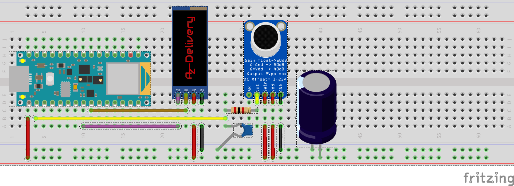
Manufacturing process
- Control Two Stepper Motors with Arduino Nano & Joystick – Simple Tutorial
- Build a Handheld Geiger Counter Using Arduino Nano
- Build an Arduino Nano-Based Eating Robot – Step-by-Step Guide
- Real-Time Arduino Weather Clock: OLED Display for Time, Date & Temperature
- Compact Programmable Pocket Power Supply with OLED Display – Arduino Compatible
- Build a Credit‑Card‑Sized Arduboy Clone with Arduino Nano & I2C OLED
- Arduino Nano‑Powered Spot Welder: DIY Precision Welding Control
- Build an RGB Matrix Audio Visualizer Using Arduino – Step‑by‑Step Guide
- Build a 7‑Segment Clock with Arduino Nano, DS3231 RTC, and LDR Auto‑Brightness
- Build an IR Sensor Project with Arduino UNO – Simple Guide