


Automated Soldering Robotic Arm: Precision, Speed, and DIY Build Guide
Components and supplies
| × | 1 | ||||
 |
| × | 1 | |||
| × | 1 | ||||
| × | 1 | ||||
| × | 1 | ||||
 |
| × | 1 |
Necessary tools and machines
 |
| |||
|
Apps and online services
 |
| |||
 |
|
About this project
IntroThe Idea of this project came to my mind accidentally when I was searching for the different abilities of robotic arms, then I found that there is a few who covers this area of usage (Automated Welding & Soldering Robotic Arm).
Actually I had an experience before for building similar projects, but this time the project was very useful and effective.
Before decided the shape of it I saw a lot of applications and other projects especially in the industry field, Open source projects helped me a lot to find out the right and suitable shape.
That’s because of the science behind the visual feeding for our brains.
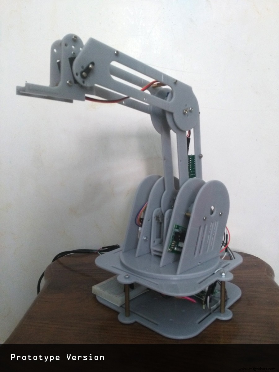
Step 1: DesignAt first I saw a lot of professional projects that wasn’t able to implement because the complexity of it.
Then I decided to see to make my own product inspired by the other projects, so I used Google Sketch up 2017 pro. Each part was designed to assemble beside each other in a specific order as shown in the next picture.
And before assembling it I had to test the parts and choose the suitable soldering iron, this happen by drawing a virtual finishing project as a guide for me.
These draws shows the actual finishing life size shape and the correct dimensions of each part to choose the right soldering iron.
Step 2: Operating and InstallationDuring the work I faced some obstacles we have to announce about it.
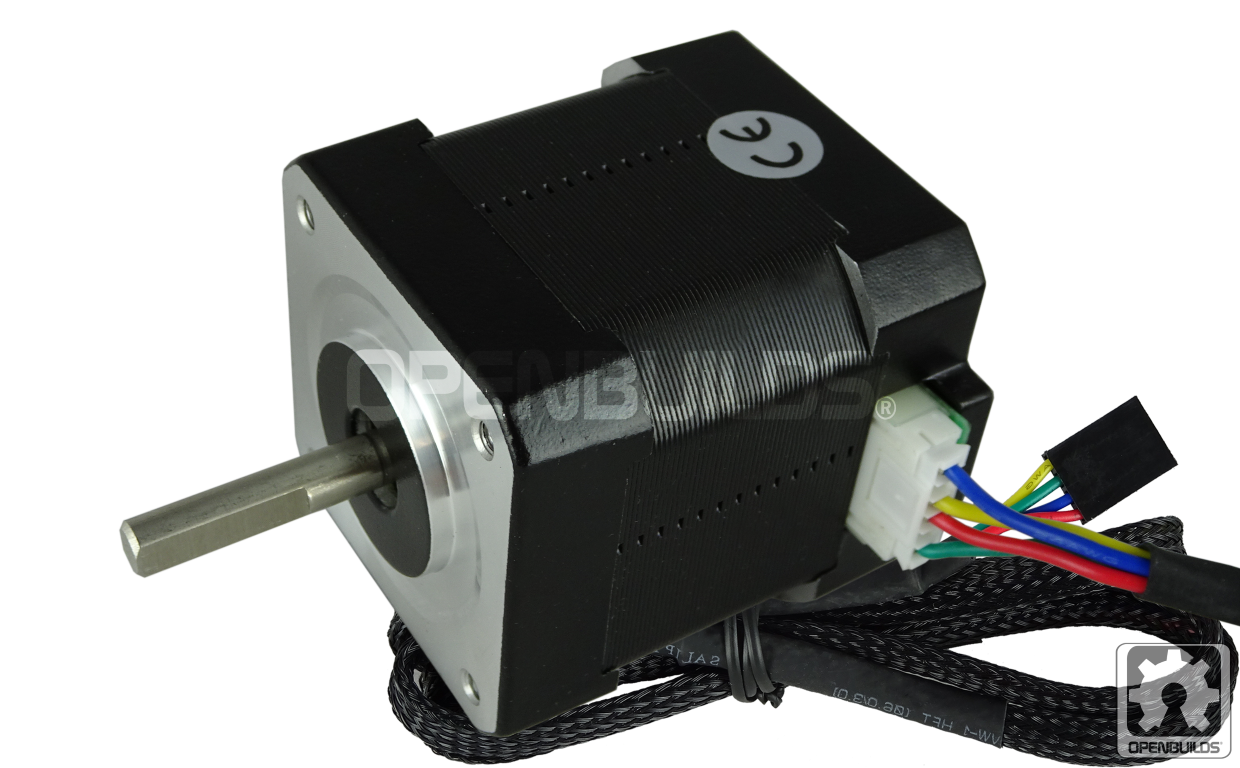
1. The arms was too heavy to be hold by the small stepper motors, and we fixed this in the next version or laser cut print.
2. Because the model was made from plastic material the friction of rotating base was high and the movements wasn’t smooth.
The first solution was to buy a bigger stepper motor that able to bear the weight and friction, and we re-designed the base to fit a bigger stepper motor.
Actually theproblem stills and the bigger motor did not fix it, and that was because the friction between two plastic surfaces beside we can't adjust the pot by percent. The maximum rotation position is not the maximum current that the driver can provide. You must use the technique shown by the manufacturer, where you measure the voltage while turning the pot.
Then I resorted to change the base design totally and put a servo motor with metal gear instated of gears mechanism.
3. voltage
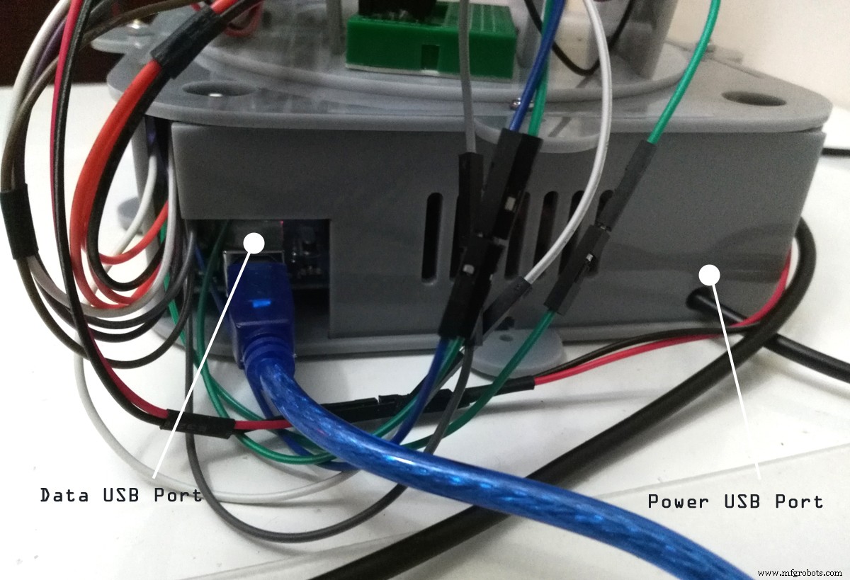
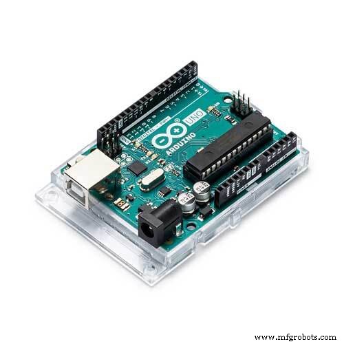
The Arduino board can be supplied with power either from the DC power jack (7 - 12V), the USB connector (5V), or the VIN pin of the board (7-12V). Supplying voltage via the 5V or 3.3V pins bypasses the regulator, and we decided to buy special USB cable that support 5 volt from the PC or any power supply.
so The stepper motors and the other components works properly with only 5 volt and to secure the parts from any problem we fix step down module.
The step down module is a buck converter (step-down converter) is a DC-to-DC power converter which steps down voltage (while stepping up current) from its input (supply) to its output (load) and also keep the stability or the voltage.
Step 3: Modifications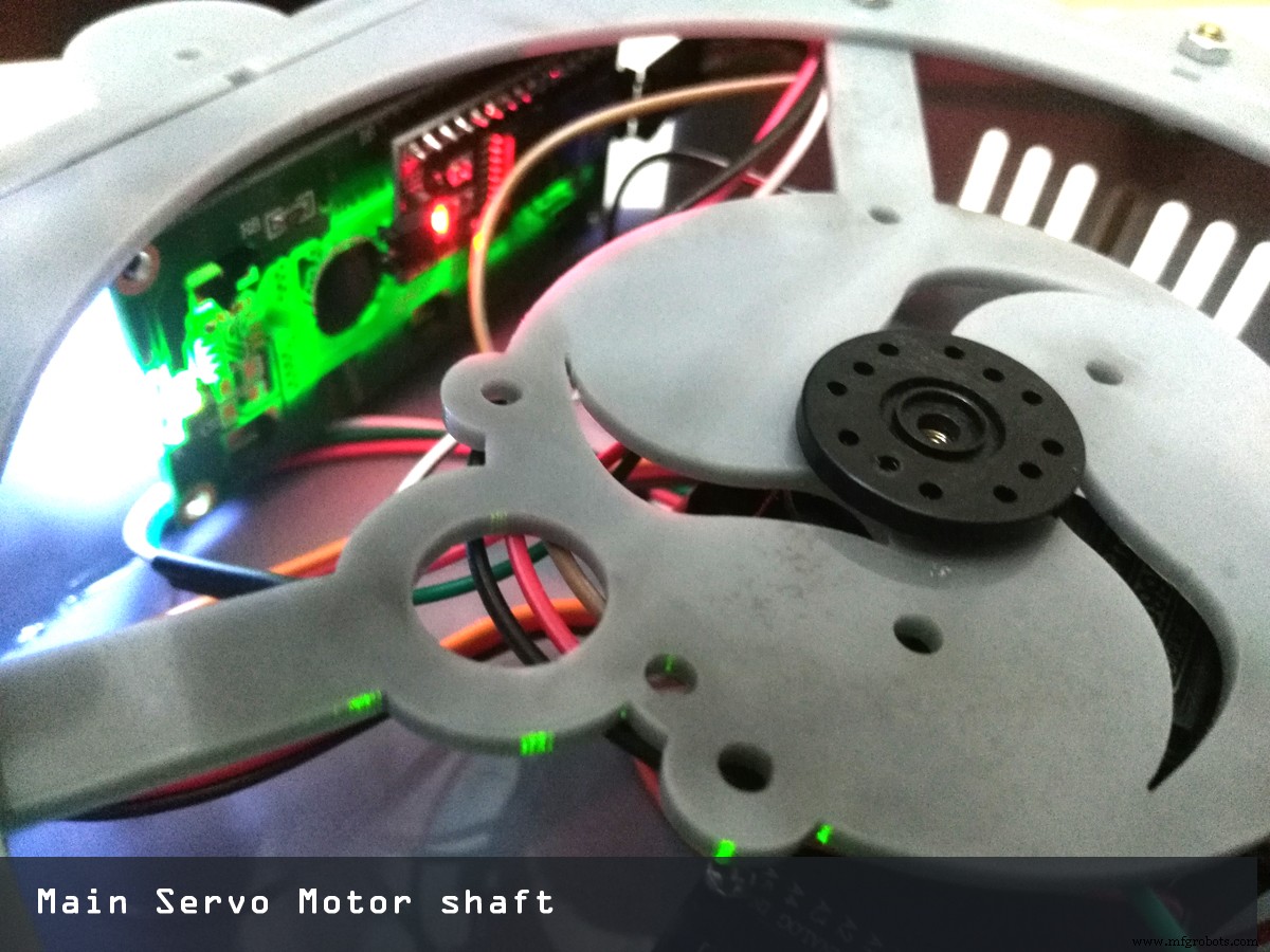
After some modifications we changed the design of the model by reducing arms size and make a suitable hole for servo motor gear as shown.
And while testing the servo motor succeeded to rotate the weight 180 degrees correctly because its high torque means a mechanism is able to handle heavier loads. How much turning force a servomechanism can output depends on design factors—supply voltage, shaft speed, etc.
Also using I2c was nice because it only uses two pins, and you can put multiple i2c devices on the same two pins. So for example, you could have up to 8 LCD backpacks+LCDs all on two pins! The bad news is that you have to use the 'hardware' i2c pin.
Step 4: Soldering Iron Holder or Gripper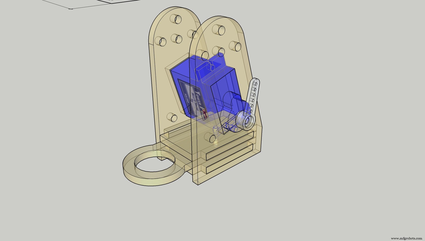
The gripper was fixed by using metal gear servo motor to bear the weight of the soldering iron.
servo.attach(9, 1000, 2000);
servo.write (constrain (angle, 10, 160)) ;
At first we had an obstacle that was motor shaking and vibrating until we found a tricky code that give constrains angels.
Because not all servos have a full 180 degreesof rotation. Many do not.
So we wrote a test to determine where the mechanical limits are. Use servo.write Microseconds instead of servo.write I like this better because it lets you use 1000-2000 as the base range. And many servos will support outside that range, from 600 to 2400.
So, we tried different values and see where you get the buzz that tells you have reached the limit. Then only stay within those limits when you write. You can set those limits when you use servo.attach(pin, min, max)
Find the true range of movement and make sure the code doesn't try to push it past the end stops, the constrain () Arduino function is useful for this.
Step 5: Coding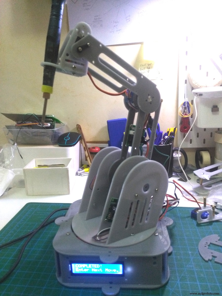
The Arduino using libraries environment can be extended through the use of libraries, just like most programming platforms. Libraries provide extra functionality for use in sketches, e.g. working with hardware or manipulating data. To use a library in a sketch.
#include AccelStepper.h#include MultiStepper.h
#include Servo.h
#include Wire.h
#include LiquidCrystal_I2C.h
Code
- Steppers X Y Z code
Steppers X Y Z codeArduino
#include "AccelStepper.h"

// AccelStepper Setup
AccelStepper stepperX(1, 2, 3);   // 1 = Easy Driver interface
                                  // UNO Pin 2 connected to STEP pin of Easy Driver
                                  // UNO Pin 3 connected to DIR pin of Easy Driver

AccelStepper stepperZ(1, 5, 6);   // 1 = Easy Driver interface
                                  // UNO Pin 5 connected to STEP pin of Easy Driver
                                  // UNO Pin 6 connected to DIR pin of Easy Driver


AccelStepper stepperY(7, 8, 9);   // 1 = Easy Driver interface
                                  // UNO Pin 5 connected to STEP pin of Easy Driver
                                  // UNO Pin 6 connected to DIR pin of Easy Driver

// Stepper Travel Variables
long TravelX;  // Used to store the X value entered in the Serial Monitor
long TravelZ;  // Used to store the Z value entered in the Serial Monitor
long TravelY;  // Used to store the Y value entered in the Serial Monitor

int move_finished=1;  // Used to check if move is completed


void setup() {

  Serial.begin(9600);  // Start the Serial monitor with speed of 9600 Bauds

// Print out Instructions on the Serial Monitor at Start
  Serial.println("Enter Travel distance seperated by a comma: X,Z ");
  Serial.print("Enter Move Values Now: ");

//  Set Max Speed and Acceleration of each Steppers
  stepperX.setMaxSpeed(500.0);      // Set Max Speed of X axis
  stepperX.setAcceleration(500.0);  // Acceleration of X axis

  stepperZ.setMaxSpeed(250.0);      // Set Max Speed of Z axis slower for rotation
  stepperZ.setAcceleration(250.0);  // Acceleration of Z axis

  stepperY.setMaxSpeed(250.0);      // Set Max Speed of Y axis slower for rotation
  stepperY.setAcceleration(250.0);  // Acceleration of Y axis
}


void loop() {

while (Serial.available()>0)  { // Check if values are available in the Serial Buffer

  move_finished=0;  // Set variable for checking move of the Steppers

  TravelX= Serial.parseInt();  // Put First numeric value from buffer in TravelX variable
  Serial.print(TravelX);
  Serial.print(" X Travel , ");

  TravelZ= Serial.parseInt();  // Put Second numeric value from buffer in TravelZ variable
  Serial.print(TravelZ);
  Serial.print(" Z Travel , ");

  TravelY= Serial.parseInt();  // Put Second numeric value from buffer in TravelY variable
  Serial.print(TravelY);
  Serial.println(" Y Travel ");

  stepperX.moveTo(TravelX);  // Set new move position for X Stepper
  stepperZ.moveTo(TravelZ);  // Set new move position for Z Stepper
  stepperY.moveTo(TravelY);  // Set new move position for Z Stepper

  delay(1000);  // Wait 1 seconds before moving the Steppers
  Serial.print("Moving Steppers into position...");
  }

// Check if the Steppers have reached desired position
  if ((stepperX.distanceToGo() != 0) || (stepperZ.distanceToGo() !=0) || (stepperY.distanceToGo() != 0)) {

    stepperX.run();  // Move Stepper X into position
    stepperZ.run();  // Move Stepper Z into position
    stepperY.run();  // Move Stepper y into position

  }

// If move is completed display message on Serial Monitor
  if ((move_finished == 0) && (stepperX.distanceToGo() == 0) && (stepperZ.distanceToGo() == 0) && (stepperY.distanceToGo() == 0)) {
    Serial.println("COMPLETED!");
    Serial.println("");
    Serial.println("Enter Next Move Values (0,0,0 for reset): ");  // Get ready for new Serial monitor values
    move_finished=1;  // Reset move variable
  }
}
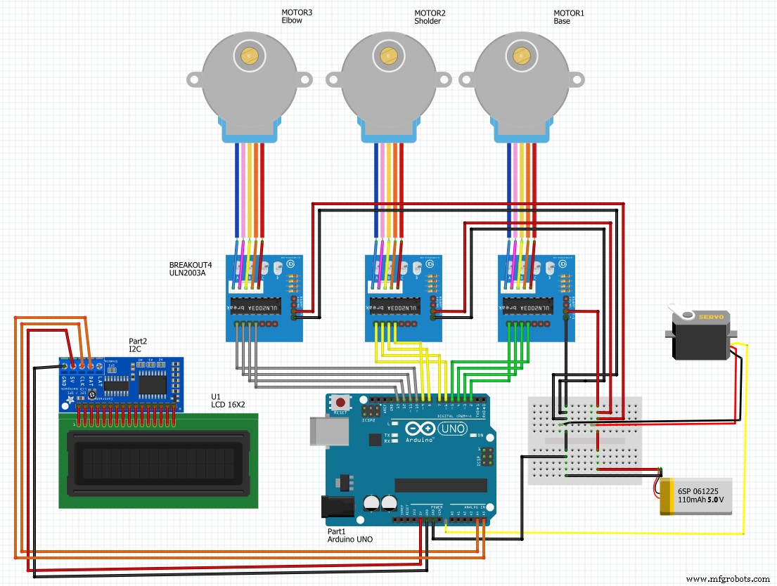
Schematics
Manufacturing process
- Understanding Servo Motors in Robotic Arms: Function, Benefits, and Impact
- Build a Functional Arduino-Powered 3D‑Printed Robotic Arm – Step‑by‑Step Guide
- Arduino-Based Nunchuk-Operated 6-DoF Robotic Arm Kit
- Build a Precise PC‑Controlled Robotic Arm with Arduino Nano & Tower Pro MG996R Servos
- Arduino Yun IoT-Enabled 5-DOF Robotic Arm with Blynk Control
- Build an Arduino Robot Arm Using Recycled Materials
- Build a Precision Robotic Arm: A Comprehensive Step-by-Step Guide
- Transform Your Logistics with Automated Robotic Palletizing Solutions
- Industrial Robotic Arms: Driving the Manufacturing Revolution
- Choosing the Right Robotic Arm Controller: Full-Size vs Compact