Build a Retro Numitron Clock with Arduino: Simple, Reliable, and Energy‑Efficient
Components and Supplies
 | | × | 1 | |
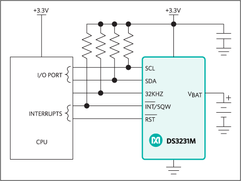 | | Maxim Integrated DS3231M – ±5 ppm, I²C Real‑Time Clock |
| × | 1 | |
| | TPIC6C595 Shift Register (High‑Current Driver) |
| × | 4 | |
| | IV9 Numitron Tube (4‑digit display) |
| × | 4 | |
 | | Generic LED (for seconds indicator) |
| × | 2 | |
 | | Capacitor 100 nF (Decoupling) |
| × | 4 | |
 | | 1N4007 – High‑Voltage, High‑Current Diode |
| × | 2 | |
 | | Slide Switch (Power / Display Intensity) |
| × | 1 | |
 | | Resistor 1 kΩ (Current Limiting) |
| × | 1 | |
Apps and Online Services
 | | Arduino IDE (Integrated Development Environment) |
| |
About this Project
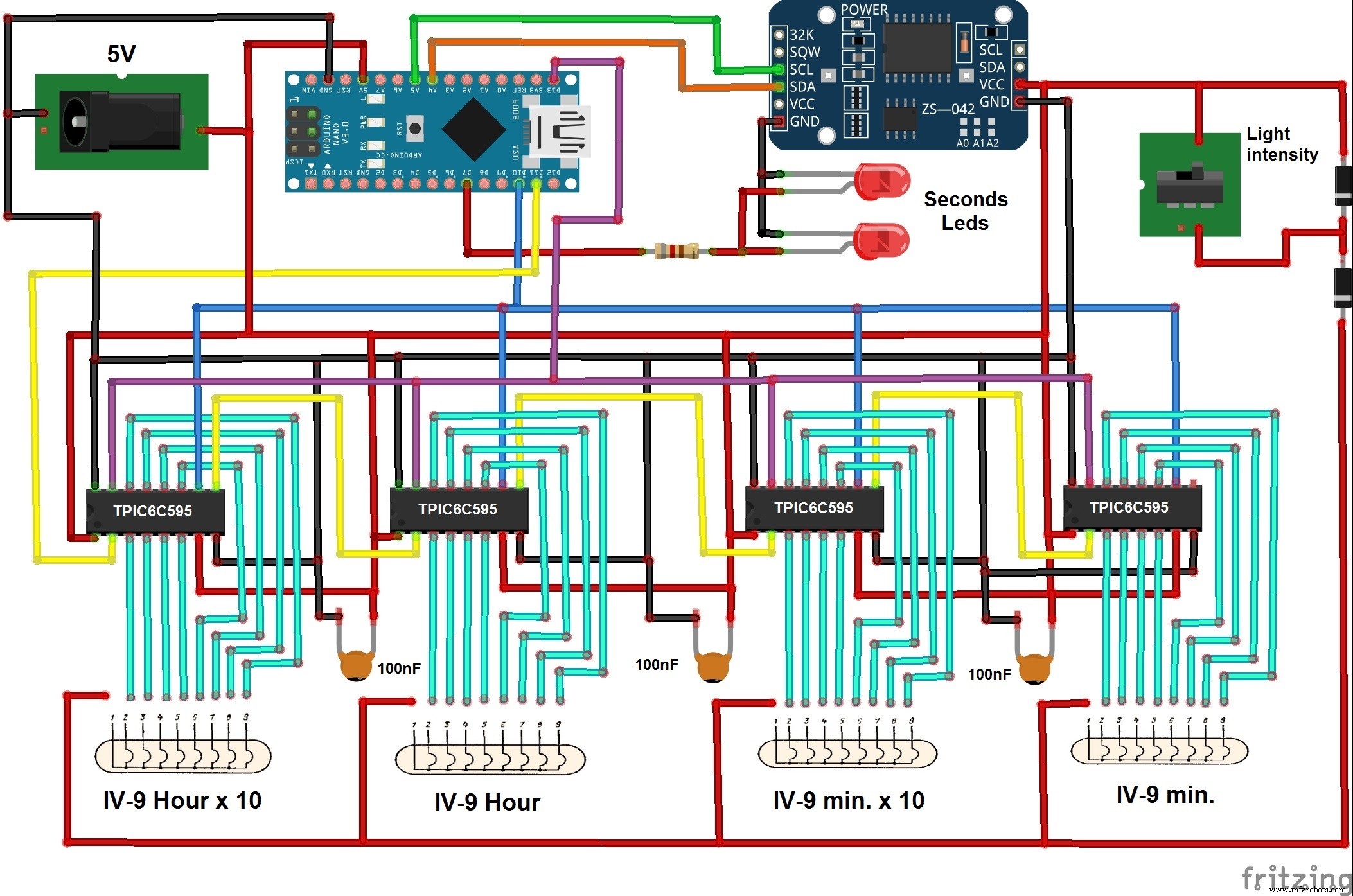
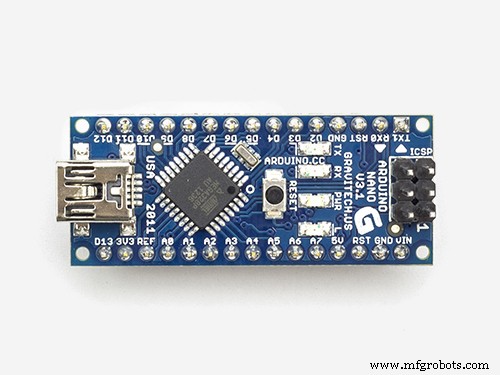
This guide walks you through building a stylish Numitron tube clock powered by an Arduino Nano, DS3231 real‑time module, and TPIC6C595 shift registers. The result is a low‑heat, reliable display that shows time, date, year, and the ambient temperature every 30 seconds.
The original concept came from this GitHub repository. During my first build, I encountered several issues: the 74HC595 shift registers overheated because the total current draw exceeded their 70 mA rating, and the program used blocking delays that caused the clock to read the RTC only once per minute.
By switching to the high‑current TPIC6C595 drivers and refactoring the firmware to use non‑blocking millis() timing, the clock now updates in real time, keeps the numitron tubes cool, and even offers a power‑saving mode that dimly illuminates the display.
Key highlights:
- Only four IV9 Numitron tubes and four TPIC6C595 drivers are required.
- The DS3231 provides accurate timekeeping and a temperature sensor, eliminating the need for an external thermometer.
- A slide switch toggles the LED‑driven seconds indicator and allows you to adjust display brightness.
- All components are inexpensive and readily available, making this a great DIY project for enthusiasts.
After assembling the circuit and uploading the code, simply mount the clock in a decorative enclosure. It will be a conversation‑starter in any workshop or display case.
Code
Arduino Code C/C++
#include <RTClib.h> // RTC with temperature for DS3231
RTC_DS3231 rtc; // instantiate DS3231

#include <Wire.h> // I2C wiring
#include <TimeLib.h> // time functions
#include <Time.h> // time library
#include <DS1307RTC.h> // additional RTC support
#include <SPI.h>

#define led 7
const int latchPin = 13; // latch pin for TPIC6C595
const int clockPin = 10; // clock pin
const int dataPin = 11; // data pin

unsigned long previousMillis = 0; // last update of display
unsigned long previousMillisDiode = 0; // last LED toggle
const long interval = 30000; // display refresh interval (30 s)
const long intervalDiode = 500; // LED blink interval

const int nums[12] = {
  0b10111110, // 0
  0b00000110, // 1
  0b01111010, // 2
  0b01101110, // 3
  0b11000110, // 4
  0b11101100, // 5
  0b11111100, // 6
  0b00001110, // 7
  0b11111110, // 8
  0b11101110, // 9
  0b11001010, // °C indicator
  0b10111000  // °C decimal point
};

// Variables to hold parsed time and temperature
int hour1, hour2, minute1, minute2, day1, day2, month1, month2, year1, year2, year3, year4, temp1, temp2;
int hourDecimal, minuteDecimal, dayDecimal, monthDecimal, year70, tempDecimal;

void setup() {
  pinMode(led, OUTPUT);
  pinMode(latchPin, OUTPUT);
  pinMode(clockPin, OUTPUT);
  pinMode(dataPin, OUTPUT);
  Serial.begin(9600);
  SPI.begin();
  digitalWrite(clockPin, LOW); // ensure clock starts low
}

void loop() {
  tmElements_t tm; // structure from DS1307RTC library
  RTC.read(tm); // read current time and temperature

  // Parse digits
  hourDecimal = tm.Hour / 10; hour1 = hourDecimal; hour2 = tm.Hour - 10 * hourDecimal;
  minuteDecimal = tm.Minute / 10; minute1 = minuteDecimal; minute2 = tm.Minute - 10 * minuteDecimal;
  dayDecimal = tm.Day / 10; day1 = dayDecimal; day2 = tm.Day - 10 * dayDecimal;
  monthDecimal = tm.Month / 10; month1 = monthDecimal; month2 = tm.Month - 10 * monthDecimal;
  year70 = tm.Year - 30; year1 = 2; year2 = 0; year3 = year70 / 10; year4 = year70 - 10 * year3;
  tempDecimal = rtc.getTemperature() / 10; temp1 = tempDecimal; temp2 = rtc.getTemperature() - 10 * tempDecimal;

  // Toggle seconds LED
  if (millis() - previousMillisDiode >= intervalDiode) {
    previousMillisDiode = millis();
    digitalWrite(led, !digitalRead(led));
  }

  // Refresh display every 30 s
  if (millis() - previousMillis >= interval) {
    previousMillis = millis();
    // Clear display (breathing effect)
    digitalWrite(clockPin, LOW);
    SPI.transfer(0b00000000);
    SPI.transfer(0b00000000);
    SPI.transfer(0b00000000);
    SPI.transfer(0b00000000);
    digitalWrite(clockPin, HIGH);
    delay(500);

    // Show date (month/day)
    digitalWrite(clockPin, LOW);
    SPI.transfer(nums[month2]); SPI.transfer(nums[month1]);
    SPI.transfer(nums[day2]); SPI.transfer(nums[day1]);
    digitalWrite(clockPin, HIGH);
    delay(1500);

    // Clear again
    digitalWrite(clockPin, LOW);
    SPI.transfer(0b00000000); SPI.transfer(0b00000000); SPI.transfer(0b00000000); SPI.transfer(0b00000000);
    digitalWrite(clockPin, HIGH);
    delay(500);

    // Show year (YY)
    digitalWrite(clockPin, LOW);
    SPI.transfer(nums[year4]); SPI.transfer(nums[year3]);
    SPI.transfer(nums[year2]); SPI.transfer(nums[year1]);
    digitalWrite(clockPin, HIGH);
    delay(1500);

    // Clear again
    digitalWrite(clockPin, LOW);
    SPI.transfer(0b00000000); SPI.transfer(0b00000000); SPI.transfer(0b00000000); SPI.transfer(0b00000000);
    digitalWrite(clockPin, HIGH);
    delay(500);

    // Show temperature (°C)
    digitalWrite(clockPin, LOW);
    SPI.transfer(0b10111000); // decimal point
    SPI.transfer(0b11001010); // °C symbol
    SPI.transfer(nums[temp2]); SPI.transfer(nums[temp1]);
    digitalWrite(clockPin, HIGH);
    delay(1500);

    // Final clear
    digitalWrite(clockPin, LOW);
    SPI.transfer(0b00000000); SPI.transfer(0b00000000); SPI.transfer(0b00000000); SPI.transfer(0b00000000);
    digitalWrite(clockPin, HIGH);
    delay(500);
  } else {
    // Regular time display (HH:MM)
    digitalWrite(clockPin, LOW);
    SPI.transfer(nums[minute2]); SPI.transfer(nums[minute1]);
    SPI.transfer(nums[hour2]); SPI.transfer(nums[hour1]);
    digitalWrite(clockPin, HIGH);
  }
}
Schematics