


Custom 4×4 Tic Tac Toe Visiting Card PCB – Design, Build, and Code Guide
Overview
This tutorial walks you through creating a custom business‑card‑sized PCB that doubles as a 4×4 tic‑tac‑toe game. The front side displays the EDISON SCIENCE CORNER logo, social‑media icons, and a QR code linking to a YouTube channel. Flip the card to reveal a fully functional game circuit powered by an ATmega328, NeoPixel LEDs, and tactile switches.
Components & Supplies
| Item | Qty |
|---|---|
| Microchip ATmega328P‑AU | 1 |
| NeoPixel RGB LED Strip (WS2812B) | 16 (4×4) |
| Tactile Switches, Top‑Actuated | 16 |
| Custom PCB (JLCPCB) | 1 |
| Arduino UNO (for programming) | 1 |
| USB Micro‑Female | 1 |
| Capacitors 22 pF (0805) | 2 |
| Capacitors 100 nF (0805) | 2 |
| Resistors 1 kΩ (0805) | 3 |
| Resistor 10 kΩ (0805) | 1 |
| 16 MHz Crystal | 1 |
| LEDs (SMD 0805) | 2 |
Necessary Tools & Machines
- Soldering iron (generic)
- Lead‑free solder wire
- Solder flux
- Jumper wire kit (5 cm, 10 pcs)
Apps & Online Services
- Arduino IDE
- EasyEDA – PCB design platform
- JLCPCB – low‑cost PCB fabrication (start at $2 for 5 boards)
Step 1: Design & Print the PCB
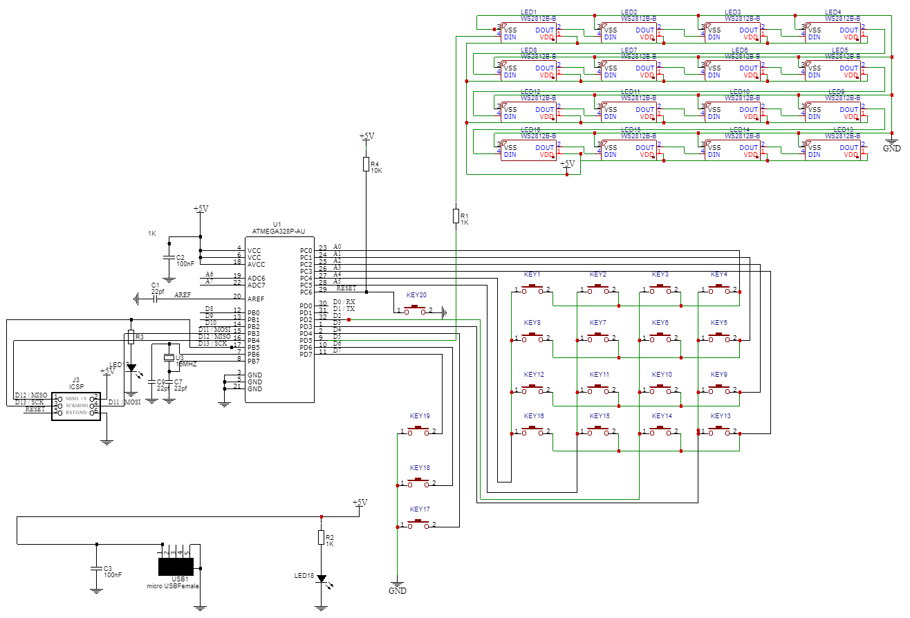
Using EasyEDA, I designed a 89 mm × 50 mm board (standard business card size) and routed a 4×4 tic‑tac‑toe matrix. The schematic uses an ATmega328 as the core microcontroller and integrates 16 WS2812B LEDs and 16 tactile switches. After finalizing the layout, I exported the Gerber files and uploaded them to JLCPCB. With a 0.8 mm black board thickness, the finished PCB arrived in two weeks, meeting the expected quality for hobbyist projects.
Step 2: Gather Components
Refer to the components list above. All parts are common, inexpensive, and can be sourced from electronics distributors such as Digi‑Key, Mouser, or AliExpress.
Step 3: Soldering
Begin by soldering the USB micro‑female connector, then place the ATmega328 and supporting passive components. Next, solder the NeoPixel LED strip and align each LED with its corresponding tactile switch. Carefully solder all 16 switches, ensuring correct orientation. The entire assembly takes roughly one hour for a skilled hobbyist.
Step 4: Programming
Connect the board to a PC via USB. Upload the following sketch using the Arduino IDE:
The sketch initializes the 16‑LED array, handles keypresses from the 4×4 keypad matrix, and implements a simple win‑detector. Player 1 uses green LEDs, Player 2 uses blue LEDs. In the event of a win, the board flashes the winning color; if the board fills without a winner, it flashes red.
Step 5: Play & Enjoy
Flip the card to reveal the game side. Each button press lights the corresponding LED. The game follows classic tic‑tac‑toe rules but with a 4×4 grid and color indicators. Enjoy a unique, portable game that doubles as a conversation starter at conferences and networking events.
Code
Below is the full Arduino sketch (C/C++) used in this project. It includes keypad handling, LED control, and win‑logic.
#include <Keypad.h>
#include <FastLED.h>

#define LED_PIN     5
#define NUM_LEDS    16
#define LED_TYPE    WS2812B
#define COLOR_ORDER GBR
#define BRIGHTNESS  30

CRGB leds[NUM_LEDS];

int player = 1;
char board[16] = {'1','2','3','4','5','6','7','8','9','10','11','12','13','14','15','16'};
char key;
int moveCount = 0;

const byte ROWS = 4;
const byte COLS = 4;
char hexaKeys[ROWS][COLS] = {{'1','2','3','A'},{'4','5','6','B'},{'7','8','9','C'},{'*','0','#','D'}};
byte rowPins[ROWS] = {A0,A1,A2,A3};
byte colPins[COLS] = {A4,A5,2,3};
Keypad customKeypad = Keypad(makeKeymap(hexaKeys), rowPins, colPins, ROWS, COLS);

void setup(){
  Serial.begin(9600);
  LEDS.addLeds<LED_TYPE, LED_PIN, COLOR_ORDER>(leds, NUM_LEDS);
  FastLED.setBrightness(BRIGHTNESS);
  // Light up all LEDs in green, then blue, to confirm functionality
  for(int i=0;i<3;i++){
    for(int j=0;j<NUM_LEDS;j++) leds[j] = (i%2==0) ? CRGB::Green : CRGB::Blue;
    FastLED.show();
    delay(500);
  }
  FastLED.clear();
}

void loop(){
  key = customKeypad.getKey();
  if(key && player==1){
    int idx = keyToIndex(key);
    leds[idx] = CRGB::Green;
    FastLED.show();
    board[idx] = 'X';
    if(checkWinner('X')){ announceWinner(1); }
    player = 2;
    delay(1000);
  }
  if(key && player==2){
    int idx = keyToIndex(key);
    leds[idx] = CRGB::Blue;
    FastLED.show();
    board[idx] = 'O';
    if(checkWinner('O')){ announceWinner(2); }
    player = 1;
    moveCount++;
    delay(1000);
  }
  if(moveCount==8){
    announceDraw();
  }
}

int keyToIndex(char k){
  switch(k){
    case '1': return 0; case '2': return 1; case '3': return 2; case 'A': return 3;
    case '4': return 4; case '5': return 5; case '6': return 6; case 'B': return 7;
    case '7': return 8; case '8': return 9; case '9': return 10; case 'C': return 11;
    case '*': return 12; case '0': return 13; case '#': return 14; case 'D': return 15;
  }
  return -1;
}

bool checkWinner(char mark){
  const int lines[10][4] = {{0,1,2,3},{4,5,6,7},{8,9,10,11},{12,13,14,15},
                            {0,4,8,12},{1,5,9,13},{2,6,10,14},{3,7,11,15},
                            {0,5,10,15},{3,6,9,12}};
  for(auto &line: lines){
    if(board[line[0]]==mark && board[line[1]]==mark && board[line[2]]==mark && board[line[3]]==mark){
      return true;
    }
  }
  return false;
}

void announceWinner(int p){
  CRGB color = (p==1) ? CRGB::Green : CRGB::Blue;
  while(true){
    for(int i=0;i<NUM_LEDS;i++) leds[i] = color;
    FastLED.show();
    delay(500);
    FastLED.clear();
    FastLED.show();
    delay(500);
  }
}

void announceDraw(){
  while(true){
    for(int i=0;i<NUM_LEDS;i++) leds[i] = CRGB::Red;
    FastLED.show();
    delay(1000);
    FastLED.clear();
    FastLED.show();
    delay(500);
  }
}
Schematics
All design files, BOM, and code are available for download.
Manufacturing process
- Multi‑Position Temperature Sensor System for Smart Home Integration
- DIY Arduino USB Gaming Controller – Build Your Own High-Performance Gamepad
- Build a Touchscreen Tic‑Tac‑Toe Game on Arduino Due
- MotionSense: Smart Intrusion Detection with Arduino & ESP8266
- 3D Printer Fire Prevention: Smart Sensor Safety System
- Pixel Chaser: Interactive One-Tap LED Game with Arduino Nano
- Advanced Microcontrollers Lab: ESP32, Arduino, PIC, and Sensor Modules
- DIY LED Roulette Game – Build a One‑Person Arcade with Arduino Nano
- CoroFence Thermal Detector: Advanced PIR Sensor & IoT Integration
- Build a Compact CNC Machine with Arduino UNO