


Integrating a Thermocouple Sensor with the Arduino Portenta H7 Using the MAX6675 IC
Components and Supplies
 |
| × | 1 | |||
 |
| × | 1 | |||
 |
| × | 1 |
Apps and Online Services
 |
|
About this Project
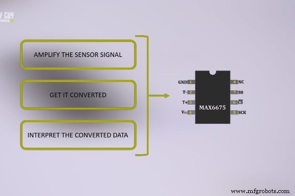
In this tutorial I walk through connecting a high‑temperature thermocouple to the Arduino Portenta H7, leveraging the MAX6675 thermocouple-to‑digital converter. The Portenta’s dual SPI ports provide a robust interface, and the MAX6675 delivers 12‑bit resolution up to 1024 °C – ideal for industrial‑grade monitoring.
What you will learn
- How a thermocouple generates voltage and how that voltage varies with temperature.
- Selecting and wiring a MAX6675 IC to the Portenta H7’s SPI bus.
- Interpreting sensor data in the Arduino IDE and visualizing it on the Serial Monitor.
Supplies
- Arduino Portenta H7
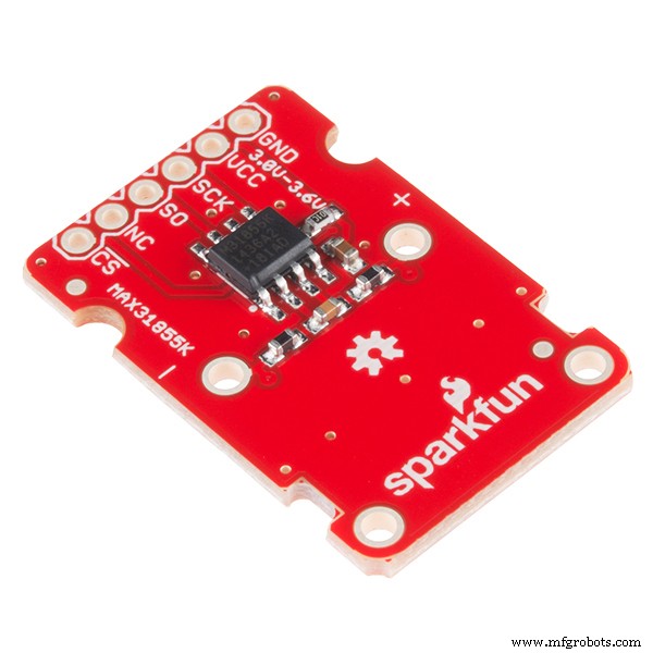
- Type‑K Thermocouple (via SparkFun MAX31855K breakout)
- Portenta Throne Board (custom PCB with dual SPI headers)
- Standard 0.1 µF decoupling capacitors
- 4‑pin screw terminal block for sensor insertion
How Thermocouple Sensors Work
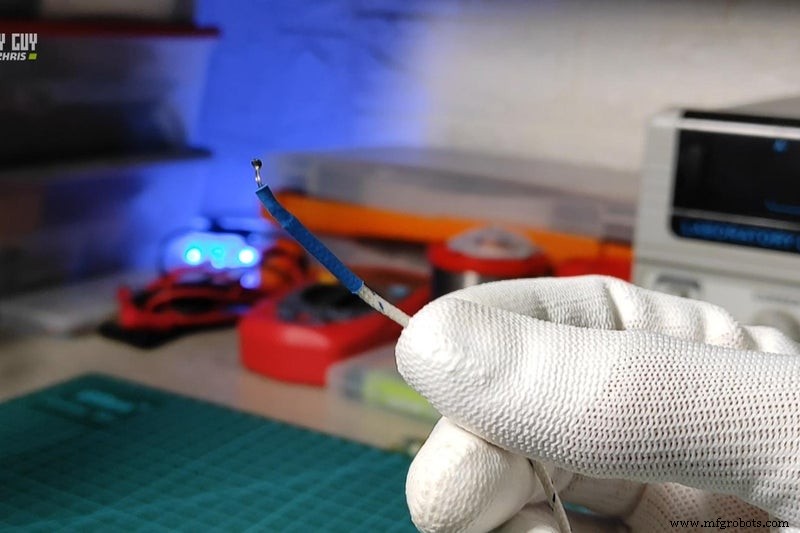
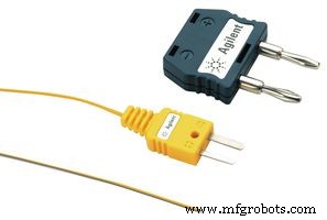
A thermocouple consists of two dissimilar metals joined at one end. When that junction is heated, a thermoelectric voltage is generated that is proportional to the temperature difference between the junction and the reference end. Because the voltage is tiny—typically a few millivolts—it must be amplified and digitized before a microcontroller can read it.
Type‑K thermocouples, made from chromel and alumel, are the most common choice for industrial temperature sensing. They cover –200 °C to 1260 °C with a typical ±1 °C accuracy when paired with a proper converter like the MAX6675.
Sensor Hardware Requirements
For reliable operation the MAX6675 must be powered from the same 3.3 V rail as the Portenta H7, and a 0.1 µF decoupling capacitor should be placed as close as possible to the IC’s VCC pin. The thermocouple wires should be inserted into the dedicated screw terminals on the breakout board, respecting polarity (red = positive).
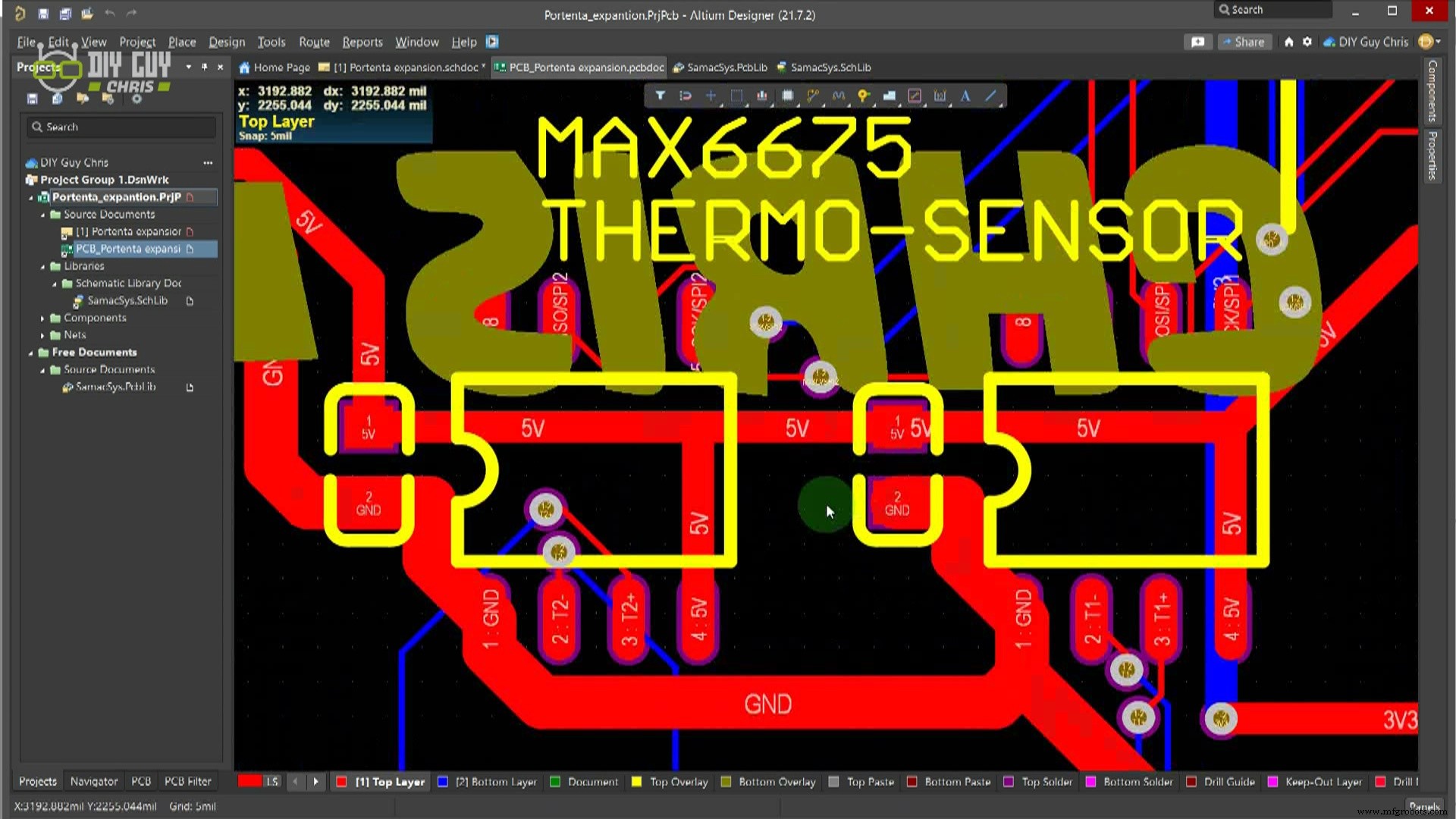
Backing to Our Throne Schematic
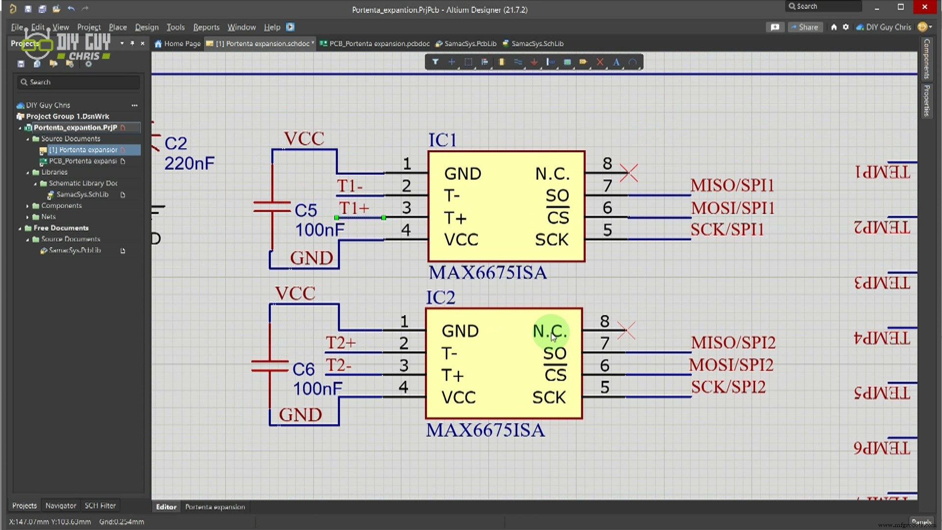
Using Altium Designer, I routed the Portenta’s two available SPI buses to the MAX6675 ICs on the custom Throne board. The first SPI interface (pins 38, 40, 42 on HD connector 2) serves the first MAX6675, while the second (pins 33, 59, 61 on HD connector 1) feeds the second IC. The design follows the MAX6675 datasheet’s recommendations for trace width and decoupling placement.
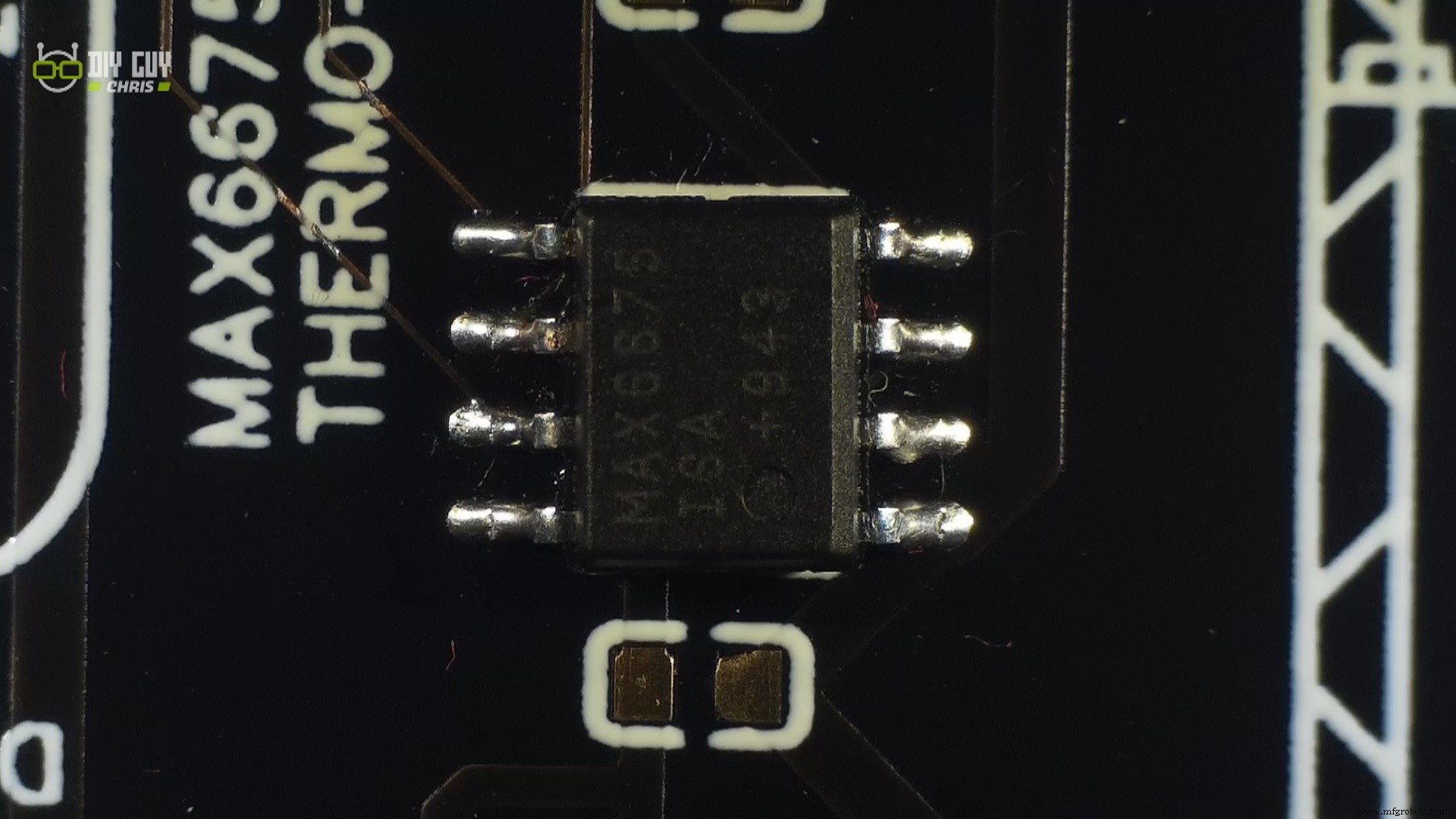
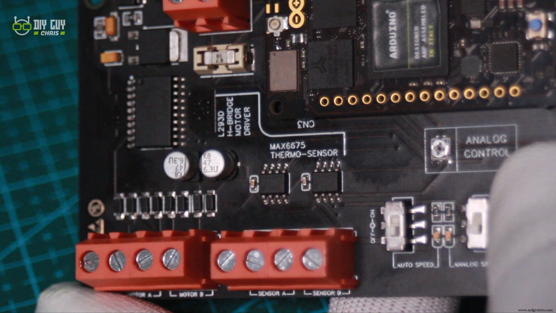
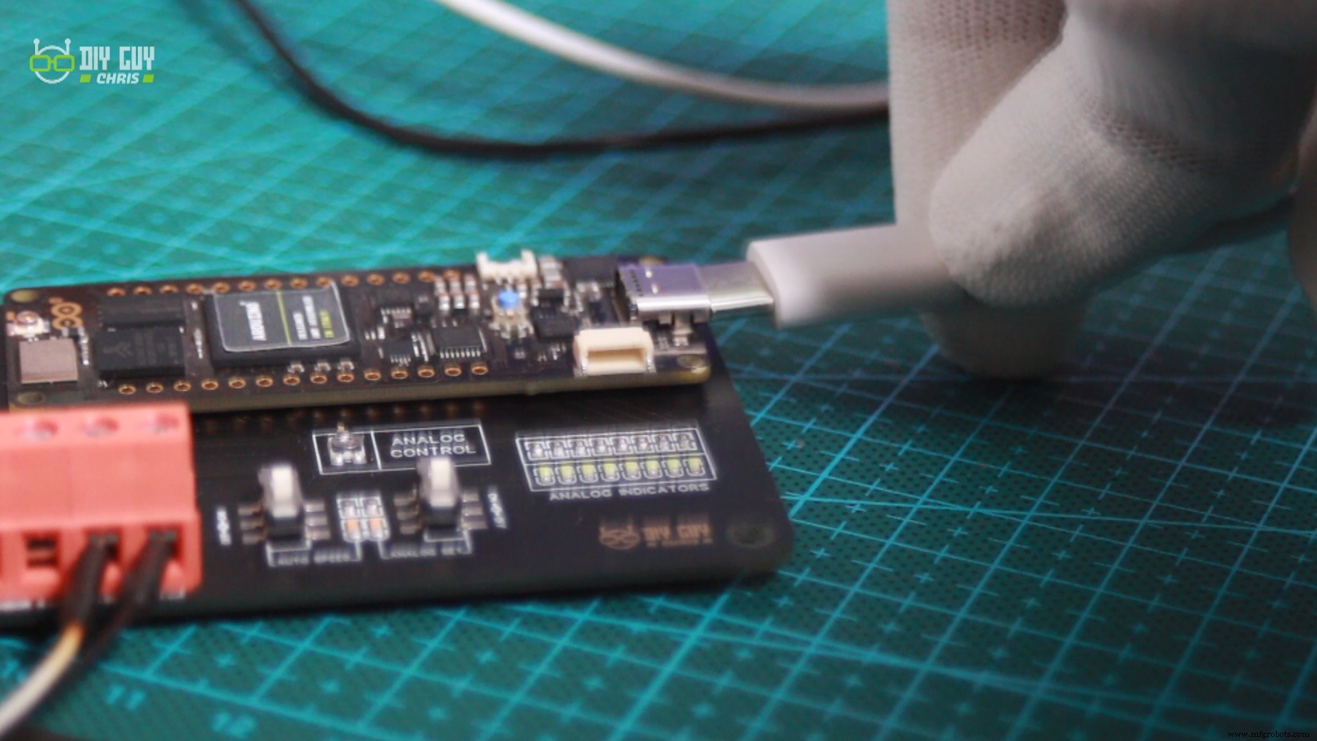
Assembly is straightforward—solder the MAX6675s and decoupling caps with a precision iron, then secure the thermocouple to the breakout using the screw terminals.
Sensor Connection Pins
When wiring the thermocouple, observe the manufacturer’s polarity marks: the red wire is +, the black wire is –. Connect the sensor to the breakout’s screw terminals, then link the breakout’s VCC, GND, DO, CS, and SCK pins to the corresponding Portenta headers as shown in the schematic.
Software and Test
The Arduino sketch uses the Adafruit MAX6675 library to communicate over SPI. After initializing the Portenta’s onboard LED (PC_7) for visual feedback, the program prints Celsius and Fahrenheit readings every second.
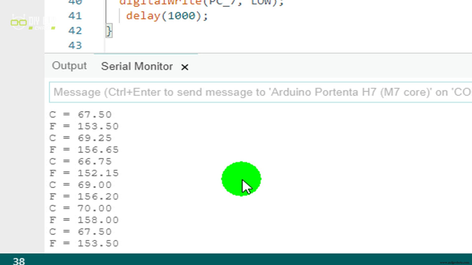
Once the sketch is uploaded, the Serial Monitor displays a steady temperature increase as the hot plate heats the thermocouple—confirming successful SPI communication and accurate conversion.
That concludes this project. Continuous experimentation with sensors and the Portenta’s versatile I/O will deepen your embedded skills. Happy hacking!
Code
- Untitled file
Untitled fileArduino
// Public domain example – a quick MAX6675 demo
// Source: www.ladyada.net/learn/sensors/thermocouple
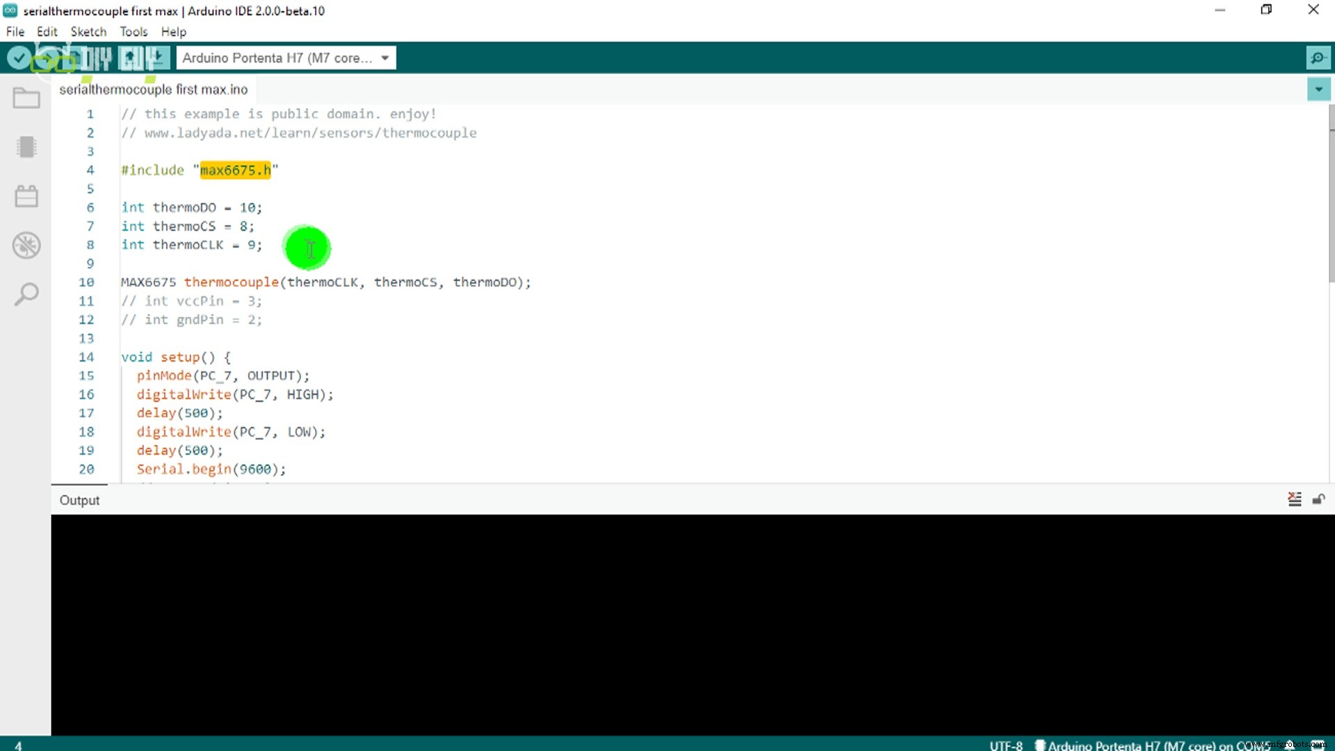
#include "max6675.h"
// SPI pins on Portenta H7 (adjust as needed)
const uint8_t thermoCLK = 9;
const uint8_t thermoCS = 8;
const uint8_t thermoDO = 10;
MAX6675 thermocouple(thermoCLK, thermoCS, thermoDO);
void setup() {
pinMode(PC_7, OUTPUT); // onboard LED
digitalWrite(PC_7, HIGH);
delay(500);
digitalWrite(PC_7, LOW);
delay(500);
Serial.begin(9600);
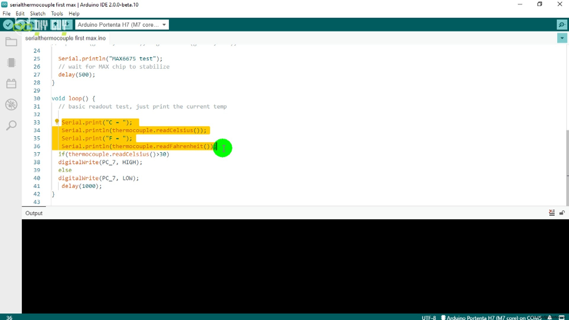
Serial.println("MAX6675 test");
delay(500); // allow chip to stabilize
}
void loop() {
float tempC = thermocouple.readCelsius();
float tempF = thermocouple.readFahrenheit();
Serial.print("C = "); Serial.println(tempC);
Serial.print("F = "); Serial.println(tempF);
// Blink LED when temperature exceeds 30 °C
digitalWrite(PC_7, tempC > 30 ? HIGH : LOW);
delay(1000);
}
Schematics
See the full schematic and PCB layout in the accompanying PDF files.
Manufacturing process
- Inductive Proximity Sensor: Circuit Design, Functionality, and Practical Applications
- Connect Multiple DS18B20 1‑Wire Sensors to a Raspberry Pi for Accurate Temperature Monitoring
- Build a Multi‑Sensor Temperature & Light Monitoring System with Raspberry Pi & DS18B20
- Build Your First IoT Project with Raspberry Pi, DHT11, and ThingSpeak
- Build an Automated Aeroponics System with Raspberry Pi and Humidity Sensor
- DHT11 Temperature & Humidity Sensor Project with LED Indicators and Piezo Speaker
- Arduino Ultrasonic Distance & Temperature Monitor with LCD Alarm System
- Build an IR Sensor Project with Arduino UNO – Simple Guide
- PIR Motion Sensor: Working Principles & Arduino Integration Guide
- Comprehensive Guide: Alcohol Sensor Pinout & Arduino Integration