32‑Band Arduino Audio Spectrum Analyzer – Linear & Pseudo‑Log Display
Components & Supplies
 | | × | 1 | |
 | | × | 1 | |
 | | × | 2 | |
 | | × | 3 | |
 | | × | 1 | |
 | | × | 1 | |
 | | × | 1 | |
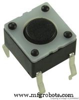 | | Tactile Switch (Top Actuated) |
| × | 1 | |
 | | Male Header 36‑Position 1‑Row (0.1") |
| × | 1 | |
Software & Online Services
About This Project
This project marks my first foray into Arduino‑based audio electronics. Inspired by Shajeeb’s audio visualizer, I expanded the display to include a 32‑band linear mode and an 11‑band pseudo‑log mode. I built custom logarithmic mapping tables in Excel and integrated them into the firmware for a more accurate frequency response.
A tactile button toggles between the two display modes, allowing quick switching during performance or experimentation.
Feel free to tweak the firmware or hardware to fit your own creative projects.
Source Code
- 32_Band_LED_Spectrum_Analyzer-009.ino
32_Band_LED_Spectrum_Analyzer-009.ino Arduino
// Modified code by Christian Suryanto, based on (c) 2019 Shajeeb TM
// HAZI TECH
// Updated by Christian Suryanto

#include <arduinoFFT.h>
#include <MD_MAX72xx.h>
#include <SPI.h>
#include <EEPROM.h>

#define HARDWARE_TYPE MD_MAX72XX::FC16_HW
#define CLK_PIN   13
#define DATA_PIN  11
#define CS_PIN    10

#define SAMPLES 64
#define MAX_DEVICES 4
#define xres 32
#define yres 8

#define PREV 0xFF02FD
#define NEXT 0xFFC23D
#define PWR 0xFFA25D

int audio_response = 35;

double vReal[SAMPLES];
double vImag[SAMPLES];
char data_avgs[xres];

int yvalue;
int displaycolumn , displayvalue;
int peaks[xres];
const int buttonPin = 6;
int state = HIGH;
int previousState = LOW;
int displaymode;
unsigned long lastDebounceTime = 0;
unsigned long debounceDelay = 50;

int MY_ARRAY[]={0, 128, 192, 224, 240, 248, 252, 254, 255};

bool EQ_ON = true;

byte eq1[32] = {40, 45, 50, 60, 65, 70, 75, 95,
               110, 110, 110, 110, 110, 110, 110, 110,
               130, 130, 130, 130, 130, 130, 130, 130,
               145, 155, 170, 180, 215, 220, 245, 255};

byte eq2[11] = {40, 70, 75, 110, 110, 140, 145, 220, 220, 230, 250};

MD_MAX72XX mx = MD_MAX72XX(HARDWARE_TYPE, CS_PIN, MAX_DEVICES);
arduinoFFT FFT = arduinoFFT();

void setup() {
    EEPROM.update(1,1);
    displaymode = EEPROM.read(1);
    ADCSRA = 0b11100101;
    ADMUX = 0b00000000;
    pinMode(buttonPin, INPUT);
    mx.begin();
    mx.control(MD_MAX72XX::INTENSITY, 0);
    delay(50);
}

void loop() {
   int numData;
   double rSum;

   for(int i=0; i<SAMPLES; i++) {
      while(!(ADCSRA & 0x10));
      ADCSRA = 0b11110101;
      int value = ADC - 512;
      value = value / 8;
      vReal[i] = value;
      vImag[i] = 0;
    }

    FFT.Windowing(vReal, SAMPLES, FFT_WIN_TYP_HAMMING, FFT_FORWARD);
    FFT.Compute(vReal, vImag, SAMPLES, FFT_FORWARD);
    FFT.ComplexToMagnitude(vReal, vImag, SAMPLES);

    int step = (SAMPLES)/xres;

    switch (displaymode) {
      case 1 : {
        numData = 32;
        for(int i=0; i<32; i++) data_avgs[i] = (vReal[i] + vReal[SAMPLES-1-i]) / 2;
        break;
      }
      case 2 : {
        numData = 11;
        data_avgs[0] = vReal[0];
        data_avgs[1] = (vReal[0] + vReal[63] + vReal[1] + vReal[0]) / 4;
        data_avgs[2] = (vReal[1] + vReal[63] + vReal[2] + vReal[62] + vReal[3] + vReal[61]) / 6;
        data_avgs[3] = (vReal[2] + vReal[62] + vReal[3] + vReal[61] + vReal[4] + vReal[60]) / 6;
        data_avgs[4] = (vReal[5] + vReal[59] + vReal[6] + vReal[58] + vReal[7] + vReal[57]) / 6;
        data_avgs[5] = (vReal[8] + vReal[56] + vReal[9] + vReal[55] + vReal[10] + vReal[54] + vReal[11] + vReal[53]) / 8;
        data_avgs[6] = (vReal[12] + vReal[52] + vReal[13] + vReal[51] + vReal[14] + vReal[50] + vReal[15] + vReal[49]) / 8;
        data_avgs[7] = (vReal[16] + vReal[48] + vReal[17] + vReal[47] + vReal[18] + vReal[46]) / 6;
        data_avgs[8] = (vReal[19] + vReal[45] + vReal[20] + vReal[44] + vReal[21] + vReal[43] + vReal[22] + vReal[42]) / 8;
        data_avgs[9] = (vReal[23] + vReal[41] + vReal[24] + vReal[40] + vReal[25] + vReal[39] + vReal[26] + vReal[38] + vReal[27] + vReal[37]) / 10;
        data_avgs[10] = (vReal[28] + vReal[36] + vReal[29] + vReal[35] + vReal[30] + vReal[34] + vReal[31] + vReal[33]) / 8;
        break;
      }
    }

    for(int i=0; i<numData; i++) {
      data_avgs[i] = data_avgs[i] / 2;
      if (EQ_ON) {
        if (displaymode==1) data_avgs[i] = data_avgs[i] * eq1[i] / 100;
        else data_avgs[i] = data_avgs[i] * eq2[i] / 100;
      }
      data_avgs[i] = constrain(data_avgs[i],0,audio_response);
      data_avgs[i] = map(data_avgs[i], 0, audio_response, 0, yres);

      yvalue = data_avgs[i];
      peaks[i] = peaks[i]-1;
      if (yvalue > peaks[i]) peaks[i] = yvalue;
      yvalue = peaks[i];
      displayvalue = MY_ARRAY[yvalue];

      if (displaymode==1) {
        displaycolumn = 31-i;
        mx.setColumn(displaycolumn, displayvalue);
      } else {
        displaycolumn = 31-(3*i);
        mx.setColumn(displaycolumn-1, displayvalue);
        mx.setColumn(displaycolumn, displayvalue);
      }
    }

    displayModeChange();
}

void displayModeChange() {
  int reading = digitalRead(buttonPin);
  if (reading == HIGH && previousState == LOW && millis() - lastDebounceTime > debounceDelay) {
    if (displaymode==1) {
      displaymode = 2;
      mx.clear();
      delay(200);
      EEPROM.update(1,2);
    } else {
      displaymode = 1;
      mx.clear();
      delay(200);
      EEPROM.update(1,1);
    }
    lastDebounceTime = millis();
  }
  previousState = reading;
}
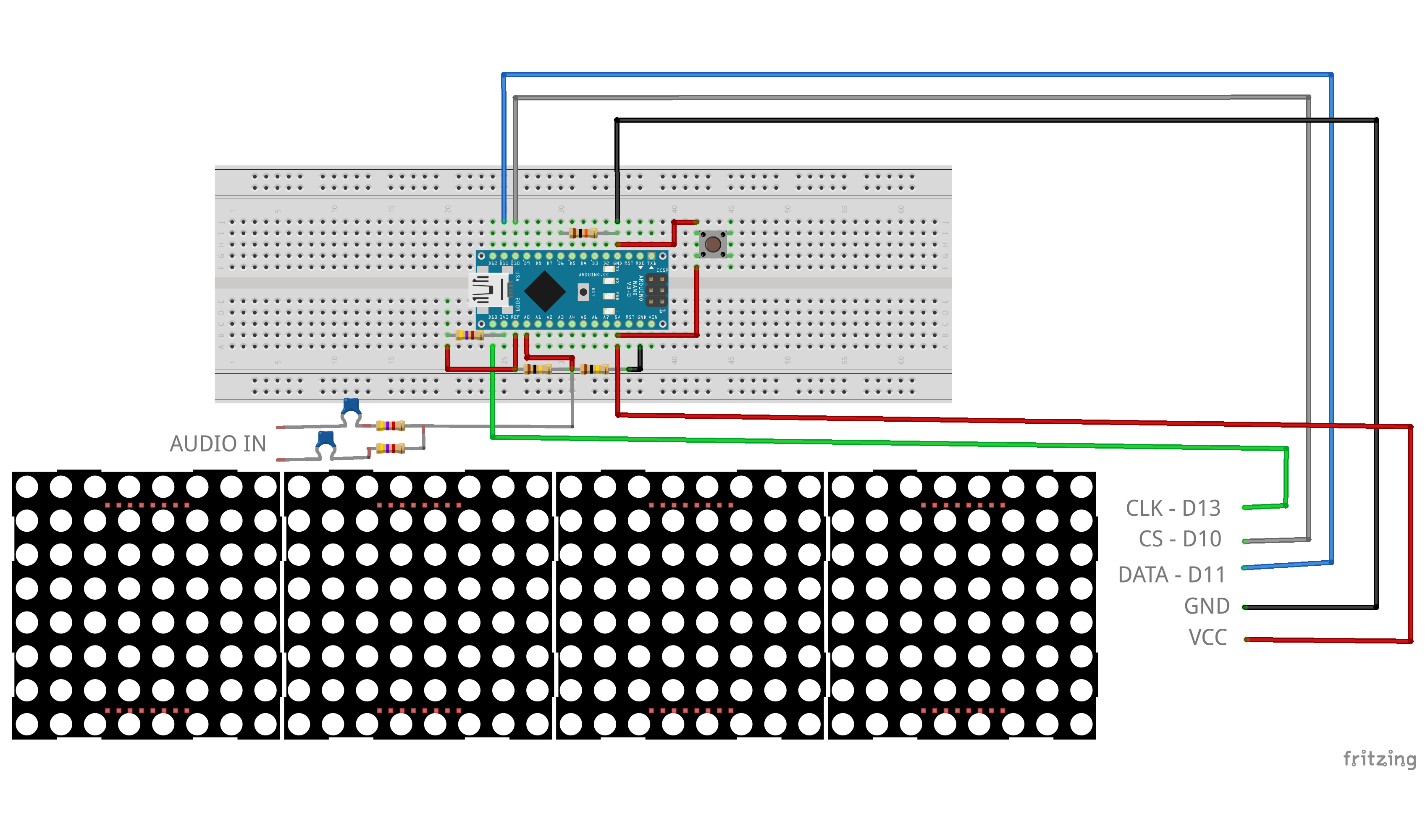
Schematics