


Save Arduino Pins: Connect a 4x3 Keypad with Only Three Connections
Components and supplies
 |
| × | 1 | |||
 |
| × | 3 | |||
| × | 1 | ||||
| × | 1 | ||||
 |
| × | 1 |
Necessary tools and machines
 |
|
Apps and online services
 |
|
About this project
IntroductionThe aim of this project is to significantly reduce the number of pins required by a numeric keypad. This is because we often need many I/O pins compared to those available on the Arduino Uno or Nanoboards.
The ordinary numerical keypads are structured in matrix: a 4x3 keypad, requires 4+3 Arduino digital pins. Numerous libraries are available on the net to use it with Arduino.
My SolutionThe solution I propose is much better because it uses only three analog inputs, with a circuit like the one shown in thefollowing figure.
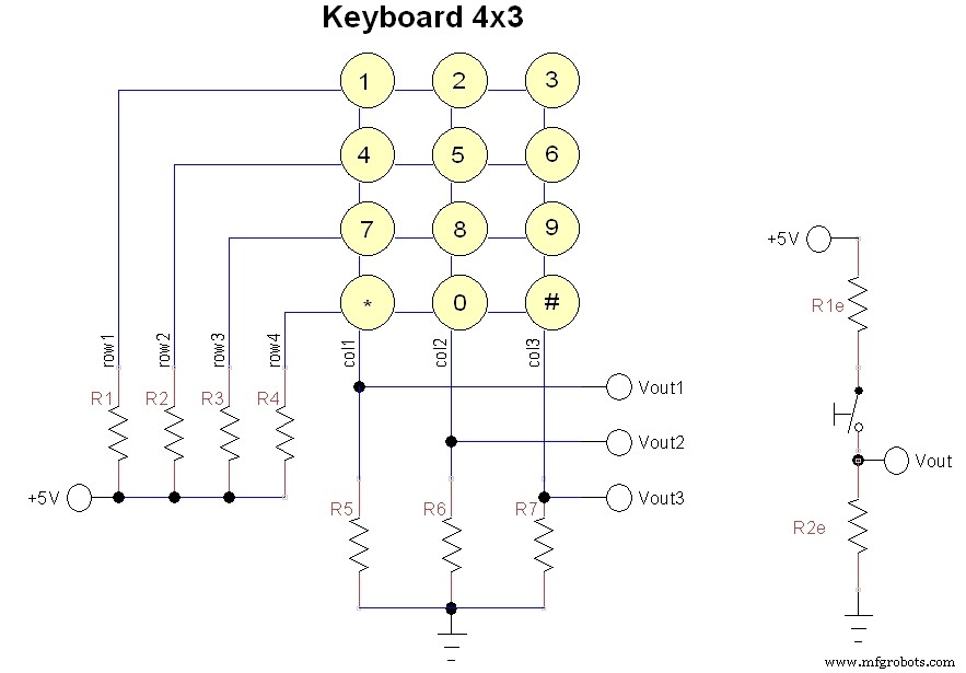
For each column there are only 4 voltage values, corresponding to each of the 4 keys, plus zero volts in case no key is pressed. In the equivalent scheme (b) the R1e indicates one of the four resistors R1-R4, while R2e is one of the three resistors R5-R7.
Now let's see how to make the four widest possible intervals. First of all the resistors R2e = R5 = R6 = R7 can be made equal, then we can set R1 = 0 to have the outputs corresponding to the first line at 5V.
With R2=330 ohm, R3= 1 k ohm, R4= 3 k ohm and R5, R6, R7= 1 k ohm, the following intervals are obtained for each output:
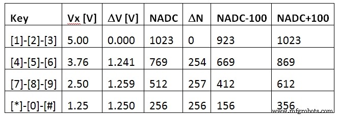
As you can see, the intervals on the threeoutputs are the largest possible and you can use six standard resistors with atolerance of ±5%. With an extra analogue input and another resistor, a 4x4keyboard can be used and so on. The following figure shows the connections withArduino.
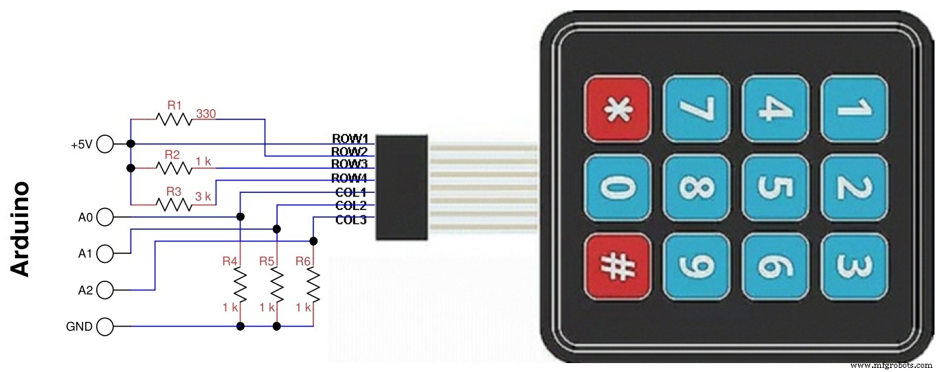
In the diagram the resistor R1 is connected toline 2 because the one on line 1 has drawn it with a wire, so the resistorreferences have been scaled by one. Pin assignments can be modified accordingto needs, as long as they are pin configurable as analog.
Of course, if Arduino is powered at 3.3V, nothing would change because the ADC converter as default uses the supplyvoltage and the ADC numbers don’t change.
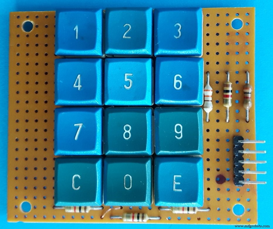
To test the program, not having a keyboardof this type, I built it with recycled keys, the figure below shows myprototype. The 5-pin right connector is used to wire it to Arduino.
Code
- Analog4x3Keybf.ino
Analog4x3Keybf.inoArduino
Simple program to test KeyPad() function/* program Analog4x3Keybf
* test for 4x3 keys keyboard with 3 analog outs
* G. Carrera - 19/11/2018
*/
// limits of keyboard output values:
const int NADCm100[4] = {923,669,412,156};
const int NADCp100[4] = {1123,869,612,356};
const char key[13] = {'1','4','7','C','2','5','8','0','3','6','9','E'};
int keyval[3];
int i,colp,val;
void setup(){
Serial.begin(9600); // used with serial monitor
}
void loop() {
char k;
k = KeyPad();// read keypad
if (k != 'N'){ // a key was pressed
Serial.print("key = ");
Serial.println(k);
delay(500);
}
}
/******** Functions used by program ********/
char KeyPad(){
// read keypad and return the char key
// key = 'N' for none
KeyScan();// read analog keyboard
if (keyval[0]+keyval[1]+keyval[2] < 40) {
return 'N';
}
else { // a key was pressed
delay(10);// antibounce
KeyScan();// reread analog keyboard
for (i=0; i < 3; i++){//identify which column it belongs to
if (keyval[i] > 40){
colp= i;
val= keyval[i];// this is the corresponding value
for (int j=0; j < 4; j++){// identify which key was pressed on the column
if (val >= NADCm100[j] && keyval <= NADCp100[j]){
return key[colp*4+j];
break;
}
}
}
}
}
}
void KeyScan(){// read analog keyboard
keyval[0]= analogRead(A0);
delay(1);
keyval[1]= analogRead(A1);
delay(1);
keyval[2]= analogRead(A2);
delay(1);
}
Schematics

Manufacturing process
- Build an Italian Word Clock with Arduino Nano, NeoPixel, LCD, and RTC
- Build a Reliable Sigfox kWh Meter with Arduino MKR Fox 1200
- Bluetooth-Enabled Temperature Monitor with Arduino Nano
- Touch‑Free Gesture Lock: Secure Access with APDS‑9960 and Arduino
- Arduino Nano Companion Kit – Essential Components & Tools for DIY Electronics
- USB MIDI Adapter Kit for Arduino Micro / Leonardo – Complete Parts List
- Build an Isolated Analog Input Circuit for Arduino
- Build a TV Output Cable for Arduino UNO with Just Two Resistors
- Smart Arduino-Driven Automatic Watering System
- Advanced 9V NiMH Battery Charger – Smart, Precise, and Reliable – Version 1