Build an Isolated Analog Input Circuit for Arduino
Components and supplies
 | | × | 2 | |
 | | × | 1 | |
| | × | 1 | |
| | × | 1 | |
| | × | 1 | |
| | × | 1 | |
| | × | 1 | |
| | × | 1 | |
 | | × | 1 | |
 | | × | 1 | |
 | | × | 1 | |
| | multi turn precision potentiometer 5k ohm |
| × | 1 | |
| | × | 1 | |
| | × | 1 | |
| | × | 1 | |
 | | × | 1 | |
 | | × | 1 | |
| | × | 4 | |
| | × | 1 | |
About this project
The signals from field sensors can be affected by noise generated by power surges, lightning strikes or other EMI (Electromagnetic Interference) sources and also by ground potential differences. One method to avoid most of these problems is to use a complete isolation from the field.
The isolation of an input sensor will require a separate power supply to power the field device and the circuit that realize the insulation itself.
More details can be found in the post published in my blog: http: //ardupiclab.blogspot.it/.
Code
- Arduino interface and program
Arduino interface and programArduino
Arduino can measure the frequency in two ways:
• period measurement, using the pulsein() function;
• frequency measurement, with CPU Timer/Counters , using special libraries.
The first method uses twice the function pulsein() in order to measure the HIGH time and LOW time of the signal, with a microsecond resolution. The sum of the two measurements is the period of the signal. For a 5kHz signal, the period is 200 µs = HIGH time + LOW time = 125+75 µs. The time resolution is relatively low and the accuracy of measurement is also affected by the time of the program instructions.
The positive aspect about this method is the measurement speed which is slightly higher than the measured period. At a disadvantage, in addition to the less accuracy, it is most sensitive to the electrical grid noise (50 or 60Hz).
For these reasons, I prefer a frequency measurement with respect to the period. The measurement time is higher but you get a higher precision and precise sampling times. In addition, choosing a measurement period multiple of that of the electrical grid, it has excellent noise immunity.
I use the FreqCounter library by Martin Nawrath KHM LAB3:
http://interface.khm.de/wp-content/uploads/2009/01/FreqCounter_1_12.zip
This library uses Timer/Counter1 for counting pulses on rising edge of T1/PD5/digitalPin5 and Timer/Counter2 for the gate-time generation with 1 ms interrupts.
I chose a gate time equal to 1000 ms to mediate the count on a period of 50 or 60 mains cycles. In this case you get a resolution that is five times greater than that of Arduino Uno.#include <FreqCounter.h>
void setup() {
Serial.begin(9600); // connect to the serial port
Serial.println("Optoisolated analog input");
}
long int frq;
void loop() {
FreqCounter::f_comp= 0; // Set compensation to 0
FreqCounter::start(1000); // Start counting with gatetime of 1000ms
while (FreqCounter::f_ready == 0) // wait until counter ready
frq=FreqCounter::f_freq; // read result
Serial.println(frq); // print result
delay(100);
}
Schematics
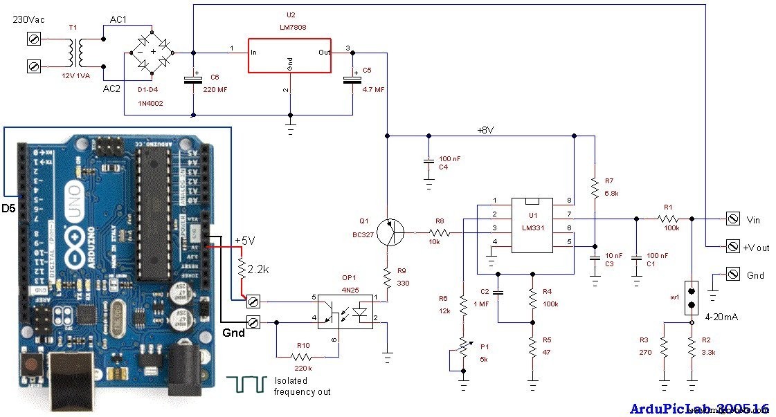
The circuit accepts an input voltage from about 20mV to 5V or a current of 4 to 20 mA (with the jumper W1 inserted). The two resistors in parallel R2 and R3 give a value of about 250 ohms, in order to have 1V to 5V for 4mA to 20mA current input.
Just three wires and a resistor are required to connect the circuit to the Arduino Uno. The output of the opto-coupler should be connected to the digital input D5 with a pull-up 2.2k resistor connected to the +5V of Arduino.
If an input range of 10V is required, a 15V power supply is necessary, so you have to change the 7808 regulator with a 7815. The transformer T1 also has to power supply the sensor, so it must have an adequate voltage and power. The trimmer P1 must be adjusted to obtain a conversion factor of about 1kHz/V.