


3‑Bit Binary Counter with 555 Timer and 4027 Flip‑Flops
3‑Bit Binary Counter with 555 Timer and 4027 Flip‑Flops
Parts & Materials
- 555 timer IC (Radio Shack catalog # 276‑1723)
- 1N914 “switching” diode (Radio Shack catalog # 276‑1122)
- Two 10 kΩ resistors
- 100 µF capacitor (Radio Shack catalog # 272‑1028)
- 4027 dual J‑K flip‑flop (Radio Shack catalog # 900‑4394)
- Ten‑segment bargraph LED (Radio Shack catalog # 276‑081)
- Three 470 Ω resistors
- 6 V battery
Caution! The 4027 IC is CMOS and highly sensitive to static discharge. Handle with anti‑static precautions.
Cross‑References
- Lessons In Electric Circuits, Volume 4, Chapter 10: “Multivibrators”
- Lessons In Electric Circuits, Volume 4, Chapter 11: “Counters”
Learning Objectives
- Configure a 555 timer as a stable square‑wave oscillator.
- Design an asynchronous down counter using a pair of J‑K flip‑flops.
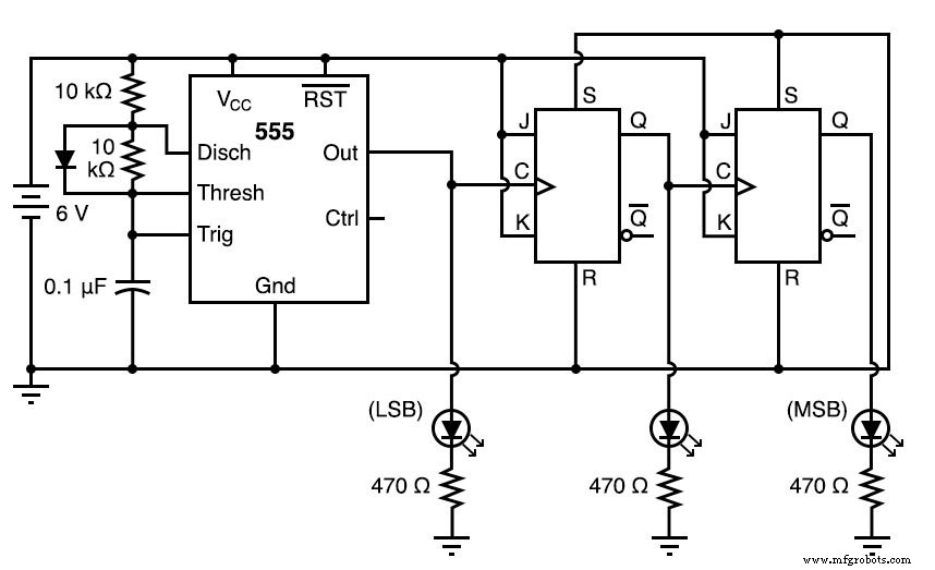
Schematic Diagram
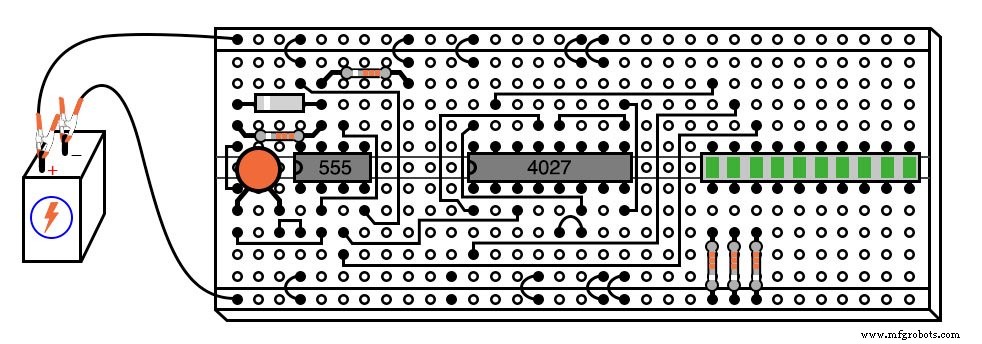
Illustration
Instructions
This circuit achieves a 3‑bit binary counter using only two J‑K flip‑flops. The 555 timer’s output supplies the least‑significant bit (LSB), allowing the counter to cycle through the pattern 111 → 110 → 101 → 100 → 011 → 010 → 001 → 000 and back to 111. Although an up‑counter is possible, it would require additional components and complexity.
The 555 timer is configured as a slow, 50 % duty‑cycle square‑wave oscillator. A 1N914 diode bypasses the lower resistor during the capacitor’s charging phase, reducing the charging time constant from 2RC to RC and ensuring a clean, symmetric waveform.
We recommend building the circuit in stages: first assemble the 555 timer, then verify its output with the LSB LED. Confirm that the LED stays on and off for equal durations and that the waveform is steady. Once the oscillator is verified, insert the 4027 IC and complete the remaining connections. Testing each sub‑circuit before powering the entire assembly dramatically reduces troubleshooting time and improves reliability.
Follow these steps to assemble the counter:
- Build the 555 Timer. Connect the 555 according to the schematic, using the 1N914 diode and 10 kΩ resistors. Power it with the 6 V battery and observe the LSB LED.
- Verify Oscillation. The LED should flash at a slow, steady rate. If the blink is irregular or absent, check the diode, resistors, and capacitor values.
- Insert the 4027 IC. Place the 4027 on the breadboard, respecting pin‑out and ensuring minimal static exposure.
- Wire the Counter. Connect the 555 output to the J‑K flip‑flop’s clock input. Wire the flip‑flop outputs to the remaining LEDs and the next flip‑flop stage as per the schematic.
- Test the Full Circuit. Apply power to the entire assembly. Observe the LED sequence: 111 → 110 → … → 000. If the sequence is correct, the counter is functioning.
By following this modular approach, you’ll gain confidence in troubleshooting and demonstrate solid understanding of oscillator design and asynchronous counter logic.
Industrial Technology
- Mastering AC Circuit Equations: Impedance, Reactance & Resonance
- Binary Addition Explained: Rules, Examples, and Its Role in Digital Computers
- Binary Subtraction Using Two's Complement
- Binary Overflow: How Sign Bits Affect Binary Addition
- Clap-Activated Switch: Build a Sound‑Responsive Circuit With and Without a 555 Timer
- 555 Timer Circuit Diagrams for 1‑15 Minute Intervals: Design, Build & Applications
- LED Roulette Circuit Using 555 Timer & CD4017 Counter – Full Diagram & Build Guide
- Build a Reliable Voltage Doubler with a 555 Timer IC – Step‑by‑Step Diagram
- Mastering the 555 Timer: A Comprehensive Guide to One-Shot Monostable Circuits
- Digital PCBs: The Backbone of Modern Electronic Systems