


Ring Counters and Johnson Counters: Design, Operation, and Practical Applications
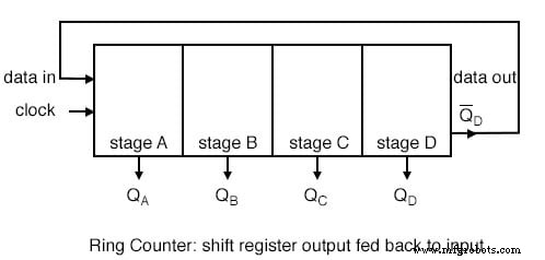
A ring counter is a special type of shift register where the output of the last stage is fed back into the first. When clock pulses are applied, the data pattern circulates indefinitely.
For instance, in a four‑stage ring counter the pattern repeats every four clock pulses, but the register must first be loaded with a data word. Loading a single “1” (e.g., 1000) is the most common and provides an easily visualized pattern.
After loading 1000, each stage’s waveform is identical except for a one‑clock‑cycle delay, as shown below.
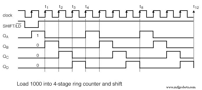
This configuration acts as a divide‑by‑4 counter; comparing the clock input with any output shows a 4:1 frequency ratio.
Dividing by Arbitrary Factors
To achieve a divide‑by‑10 counter, ten stages are required. A single “1” will circulate every ten clock pulses.
Initialization Requirements
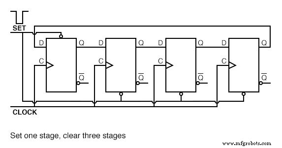
Ring counters must be initialized at power‑up because the initial state of each flip‑flop is undefined. Once initialized, the pattern should persist; however, noise can corrupt the state over time, potentially breaking the sequence.
A conventional synchronous binary counter can self‑correct and therefore is often more reliable in long‑term operation.
Comparison with Conventional Counters
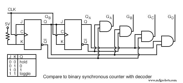
The binary counter uses two stages and requires decoder gates, whereas the ring counter is self‑decoding but needs more stages. If decoded outputs are required and most logic resides in a single shift register package, a ring counter may be attractive; otherwise, the simpler binary counter is preferable.
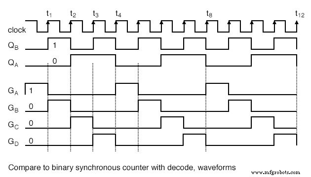
The decoded waveforms from a synchronous binary counter match those of the ring counter: (QA QB) cycles through 00, 01, 10, 11.
Johnson Counters
Also known as a switch‑tail ring counter, a Johnson counter overcomes several ring‑counter limitations. By feeding the complement (Q′) of the last stage back into the first, a Johnson counter requires only half as many stages for a given division ratio.
For example, a four‑stage Johnson counter divides the input clock by eight, whereas a four‑stage ring counter divides by four.
Johnson counters are typically cleared to all zeros on power‑up to establish a known state.
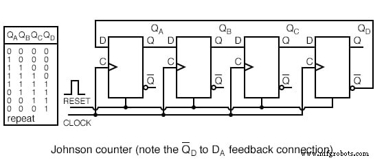
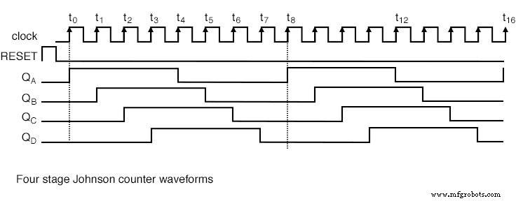
When a single “1” is introduced, the counter progresses through a sequence of four zeros followed by four ones, producing an eight‑state cycle.
Multi‑Phase Output Generation
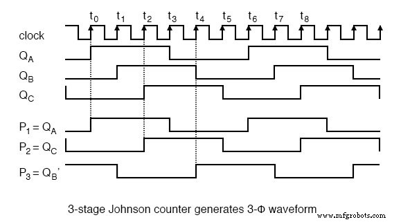
A four‑stage Johnson counter yields four overlapping 50% duty‑cycle phases. A three‑stage Johnson counter, driven by a 360 Hz clock, generates three 120°‑phased square waves at 60 Hz.
Decoding the States
Each state of a Johnson counter can be decoded with simple two‑input gates. For a 4‑stage counter, eight states are decoded using eight two‑input AND gates.
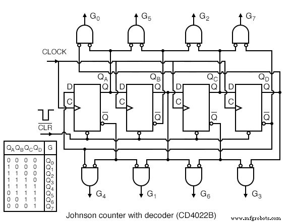
Only 2‑input decoder gates are needed regardless of counter length. Inverting the inputs to the AND gates can simplify the logic, but the diagram below follows the CD4022B datasheet closely.
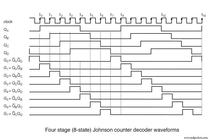
The eight decoded outputs (G0–G7) each remain active high for one clock period within the 8‑clock cycle. For example, G0 is high when both QA and QD are low.
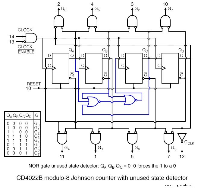
Disallowed States and Error Correction
Because a 4‑stage shift register can represent 16 binary states, only eight are valid for the Johnson counter. The remaining eight are disallowed. The CD4022B includes a disallowed‑state detector composed of two NOR gates.
In practice, the counter is reset at power‑up to avoid entering a disallowed state. If a disallowed state is encountered (e.g., 010), the NOR gates force the next input to zero, converting the state to a permissible one (e.g., 000).
After a few clocks, any disallowed state will be corrected. However, for critical applications, always reset the counter on power‑up.
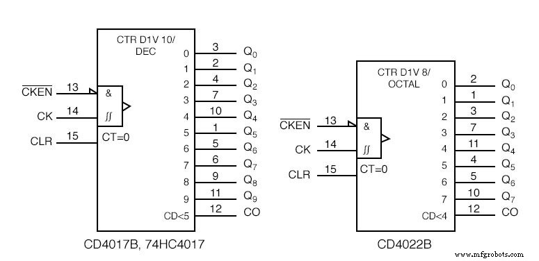
Johnson Counter Devices
Integrated circuits with decoded outputs are available for both the 4000 series and the 74HC family. The CD4017 offers ten decoded outputs (modulo‑10), while the CD4022 provides eight decoded outputs (modulo‑8). The 74HC variants operate at lower voltages (2 V–6 V) and deliver higher output drive.
- CD4017 Johnson counter with 10 decoded outputs (CD4022 Johnson counter with 8 decoded outputs)
- 74HC4017 Johnson counter, 10 decoded outputs
Practical Applications
Figure 1 demonstrates a 74HC4017 driving ten LEDs, one illuminating each fifth of a second around a ring. The 74HC4017’s 4 mA output capability (VOH = 4.6 V at 4 mA) is sufficient to light LEDs, though typical LED currents are 10–20 mA.
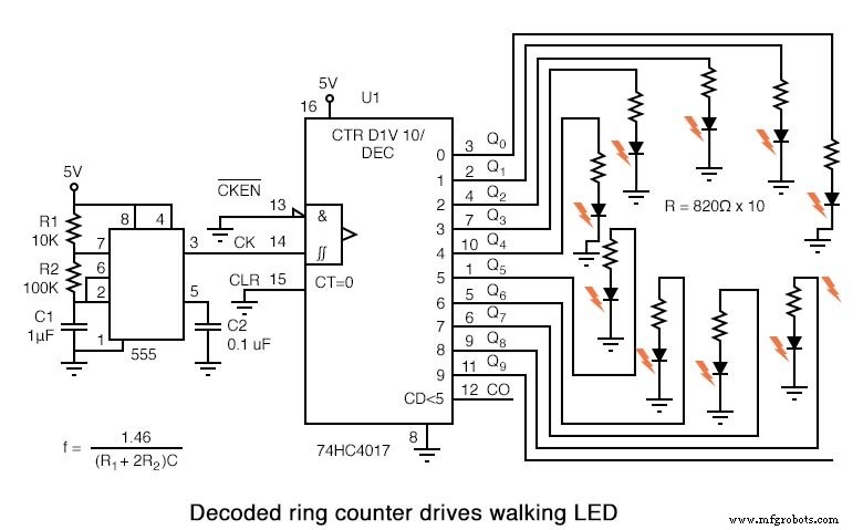
A 555 timer provides the clock pulses; an additional buffer can be inserted if the 555 cannot drive the counter’s clock input reliably.
Johnson counters can also generate 3‑phase square waves. By selecting P1 = QA, P2 = QC, P3 = QB′, the outputs are 120° apart. Low‑pass filtering and amplification can transform these into 3‑phase sine waves for power supplies or motor drives.
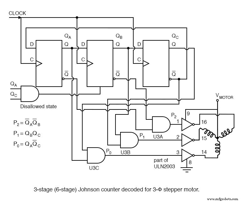
For 3‑phase stepper motors, the overlapping outputs are decoded into non‑overlapping waveforms (P0, P1, P2) suitable for driver ICs such as ULN2003 or discrete Darlington pairs.
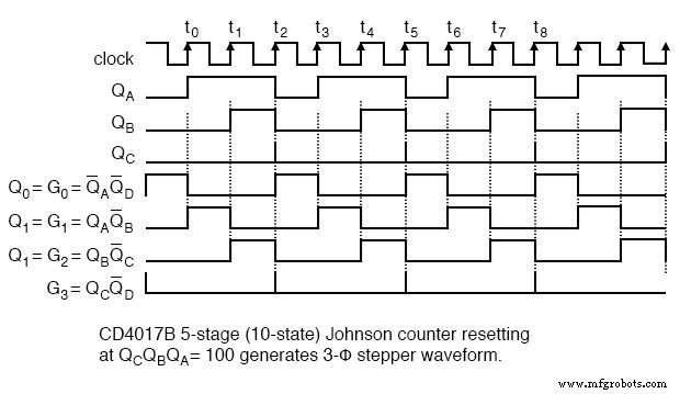
Using a single CD4017, the counter can be reset after the third count, ensuring each state lasts a full clock period before the next reset.
Related Worksheets
- Counters Worksheet
- Shift Registers Worksheet
Industrial Technology
- What Are Retaining Rings? Understanding Their Design and Applications
- 3‑Bit Binary Counter with 555 Timer and 4027 Flip‑Flops
- Designing an Asynchronous Four‑Bit Up Counter with J‑K Flip‑Flops
- Synchronous Binary Counters: Design, Up/Down Operation, and Encoder Applications
- Counter Modulus: Optimized Algorithms for Modern Systems
- Digital Ramp (Counter) ADC: Operation, Benefits, and Limitations
- Tracking ADC: Up/Down Counter for Fast, Continuous Signal Conversion
- 4‑bit Counter: Efficient Binary Counting from 0 to 15
- Verilog Ring Counter Module: Design & Testbench Example
- ToughMet® 3AT Ring AT (C72900) – High‑Strength, Corrosion‑Resistant Copper Alloy