


Designing an Asynchronous Four‑Bit Up Counter with J‑K Flip‑Flops
Previously we examined a single J‑K flip‑flop configured to count backwards in a two‑bit binary sequence (11 → 10 → 01 → 00). To build a counter that increments forward, we must analyze the forward count pattern and determine how to interconnect multiple flip‑flops.
Binary counters rely on a factor‑of‑two frequency division. J‑K flip‑flops set in toggle mode are ideal for this task. By cascading several such flip‑flops, we can generate a four‑bit binary output. The key challenge is to wire the clock inputs so that each flip‑flop toggles precisely when the preceding bit changes from 1 to 0.
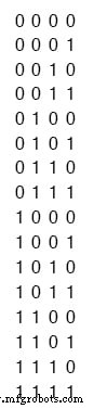
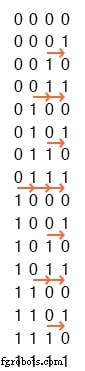
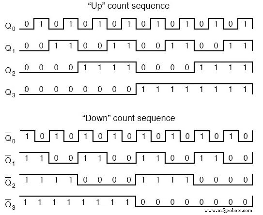
Below is the binary sequence for a four‑bit up counter. Notice that a bit toggles only when the less significant bit toggles from high to low.
Small arrows point to the moments a bit flips, indicating the preceding bit’s transition from 1 to 0.
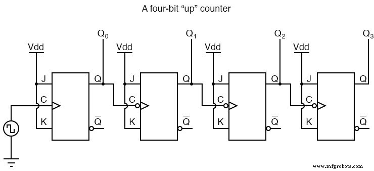
Using four J‑K flip‑flops set to always toggle, we can connect each clock input to the Q output of the preceding flip‑flop. With negative‑edge triggering (bubble symbols), the falling edge of the previous Q signal clocks the next flip‑flop at the right instant.
Four‑Bit “Up” Counter
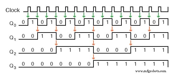
The resulting waveforms, driven by a periodic oscillator, show the expected up‑counting behavior. The first flip‑flop (Q0) toggles on every rising edge of the clock, while the duty cycle of the clock need not be exactly 50 %—the circuit remains reliable with any pulse shape.
Note that using one J‑K flip‑flop per output bit eliminates the need for a symmetrical clock signal, which is required when the clock itself is used as an output.
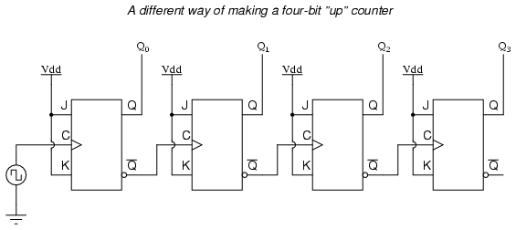
A second approach, using positive‑edge triggered flip‑flops, is to clock each flip‑flop with the Q′ output of the preceding stage. Because Q′ is always the complement of Q, a 1→0 transition on Q generates a 0→1 transition on Q′, providing the needed positive edge.
Alternative Four‑Bit “Up” Counter
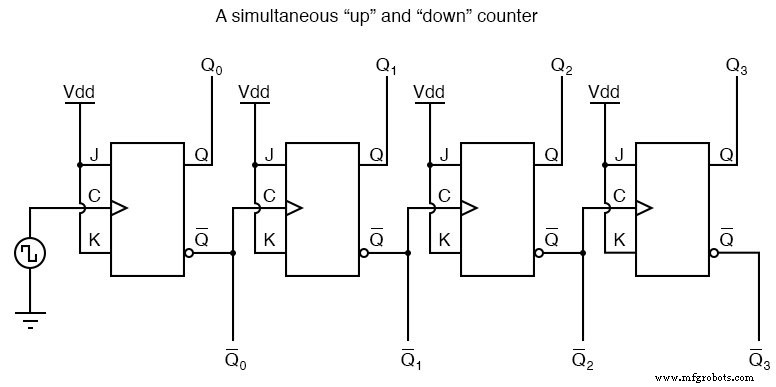
By treating the Q′ outputs as a second set of bits, the counter can simultaneously produce an up‑counting sequence on Q and a down‑counting sequence on Q′.
Simultaneous Up and Down Counter
All of these cascaded‑flip‑flop designs suffer from the ripple effect. Propagation delays accumulate as each flip‑flop toggles, so the most significant bit (MSB) lags behind the least significant bit (LSB). During a transition such as 0111 → 1000, the outputs ripple through 0110, 0100, 0000 before settling at 1000, generating transient false counts.
Disadvantage of Asynchronous Counter Circuit: Propagation Delay
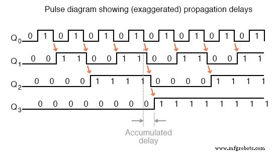
The ripple manifests as a brief cascade of state changes, which can be problematic in time‑critical applications like multiplexers or memory address decoding.
Strobe Signal Counter Circuit
To mitigate ripple, many circuits use a strobe or enable signal. The enable is tied to the clock so that the downstream device only reacts when the counter outputs are stable. For an active‑low enable, the device is disabled during the high portion of the clock pulse, which coincides with the toggle activity.
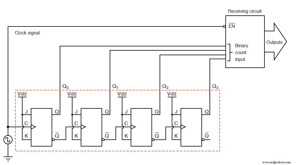
Ensuring that the clock’s high period exceeds the maximum ripple delay guarantees that the enable will activate only after the counter has fully settled.
Disadvantage of Asynchronous Counter Circuit: Limited Speed
Because propagation delays add, an asynchronous counter cannot run faster than the slowest stage plus all preceding delays. This limits the maximum operating frequency and makes synchronous counters preferable for high‑speed designs.
These limitations motivate the development of synchronous (non‑ripple) counter architectures, which will be explored next.
REVIEW
- An up counter can be built by connecting the clock inputs of positive‑edge triggered J‑K flip‑flops to the Q′ outputs of the preceding stage, or by using negative‑edge triggered flip‑flops with Q outputs. In both cases, J and K inputs are held high.
- All cascaded‑flip‑flop counters exhibit a ripple effect, producing transient false counts; such counters are called asynchronous or ripple counters.
- Strobing enables downstream circuits only when counter outputs are stable, preventing errors caused by ripple.
RELATED WORKSHEETS
Industrial Technology
- Common‑Emitter Amplifier: Design, Measurement, and Feedback Techniques
- Build a High‑Gain Differential Amplifier That Works as an Op‑Amp
- Precision Voltage Follower: Mastering Op‑Amp Feedback for Accurate Signal Tracking
- Special-Output Logic Gates: Complementary, Tristate, and Bilateral Switches
- Understanding the J‑K Flip‑Flop: Design, Logic, and Applications
- Asynchronous Flip‑Flop Inputs: Preset and Clear Functionality
- Synchronous Binary Counters: Design, Up/Down Operation, and Encoder Applications
- Ring Counters and Johnson Counters: Design, Operation, and Practical Applications
- Tracking ADC: Up/Down Counter for Fast, Continuous Signal Conversion
- Delta‑Sigma ADC: Harnessing Oversampling for Precise Analog‑to‑Digital Conversion