Enhanced Buzz Wire Game with Built‑In Score Counter – Arduino Nano Project
Components and supplies
 | | × | 1 | |
 | | × | 1 | |
 | | × | 1 | |
 | | × | 1 | |
 | | Texas Instruments Shift Register- Serial to Parallel |
| × | 1 | |
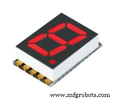 | | 7 Segment LED Display, Red |
| × | 1 | |
 | | × | 10 | |
| | × | 1 | |
About this project
After playing around with Arduino just to pass time for a while, I decided to make an enhanced version of the good old buzz wire game that counts your failures and goes nuts if you hit the wire 10 times!
Here is a video of myself sucking at my own game:
The source code is divided in three files.
In the code, a "grace period" of 500ms is set after each failure. You can modify that to give the player a bigger break after each buzz.
Also something I noticed at the end was that the LEDs are a bit too bright! Feel free to swap the two resistors used on them with stronger ones. Mine are only about 100ohms.
For the ring, I have used the end of a key-chain. The good thing about it is that you can just open it and won't have to navigate all the way back on the wire.
I hope you enjoy my project!
Code
- nervous_meter_score.ino
- score_display.ino
- game.ino
nervous_meter_score.inoArduino
int latchPin = 3;      // ST_CP [RCK] on 74HC595
int clockPin = 4;      // SH_CP [SCK] on 74HC595
int dataPin = 2;     // DS [S1] on 74HC595
const int STOP_LED = 6;
const int GO_LED = 7;
const int BUZZ = 8;
const int TOUCH = 10;

const int fail_threshold = 9;

enum Status
{
  STOP = 0,
  GO = 1
};


void setup() {
  Serial.begin(9600);
  displayInitialSetup();
  gameInitialSetup();
}


Status status = GO;
int failCounter = 0;

void loop() {


  while (failCounter > fail_threshold)
    {
      gameover();
    }

  switch (status)
  {
    case GO:
      digitalWrite(GO_LED, HIGH);
      digitalWrite(STOP_LED, LOW);
      digitalWrite(BUZZ, LOW);
      if (digitalRead(TOUCH) == HIGH)
      {
        status = STOP;
      }
      break;

    case STOP:
      digitalWrite(GO_LED, LOW);
      failCounter++;
      if (failCounter > fail_threshold)
        break;
      displayDigit(failCounter);
      Serial.println(failCounter);
      failAlarm();
      status = GO;
      break;
  }

}


byte seg_spin[6] =
{
  B10000000,
  B01000000,
  B00100000,
  B00010000,
  B00001000,
  B00000100
};
void gameover()
{
  for (int i=0; i<6; i++)
  {
    digitalWrite(BUZZ, HIGH);
    delay(5);
    digitalWrite(BUZZ, LOW);
    delay(50);
     digitalWrite(latchPin, LOW);
     shiftOut(dataPin, clockPin, LSBFIRST, seg_spin[i]);
     digitalWrite(latchPin, HIGH);
     delay(10);
  }
}
score_display.inoArduino
byte seg_digits[10] =
{
  B11111100,  // = 0
  B01100000,  // = 1
  B11011010,  // = 2
  B11110010,  // = 3
  B01100110,  // = 4
  B10110110,  // = 5
  B10111110,  // = 6
  B11100000,  // = 7
  B11111110,  // = 8
  B11100110   // = 9
};


void displayDigit(int x)
{
   digitalWrite(latchPin, LOW);
   shiftOut(dataPin, clockPin, LSBFIRST, seg_digits[x]);
   digitalWrite(latchPin, HIGH);
}

void displayInitialSetup()
{
  pinMode(latchPin, OUTPUT);
  pinMode(dataPin, OUTPUT);
  pinMode(clockPin, OUTPUT);
  displayDigit(0);
}
game.inoArduino
void gameInitialSetup()
{
  pinMode(STOP_LED, OUTPUT);
  pinMode(GO_LED, OUTPUT);
  pinMode(BUZZ, OUTPUT);
  pinMode(TOUCH, HIGH);
  digitalWrite(TOUCH, LOW);
}


void failAlarm()
{
    digitalWrite(STOP_LED, HIGH);
    beep();
    delay(150);

    digitalWrite(STOP_LED, LOW);
    digitalWrite(BUZZ, LOW);
    delay(500);
}

void beep()
{
  for(int i=0; i<3; i++)
  {
    digitalWrite(BUZZ, HIGH);
    delay(50);
    digitalWrite(BUZZ, LOW);
    delay(50);
  }
}
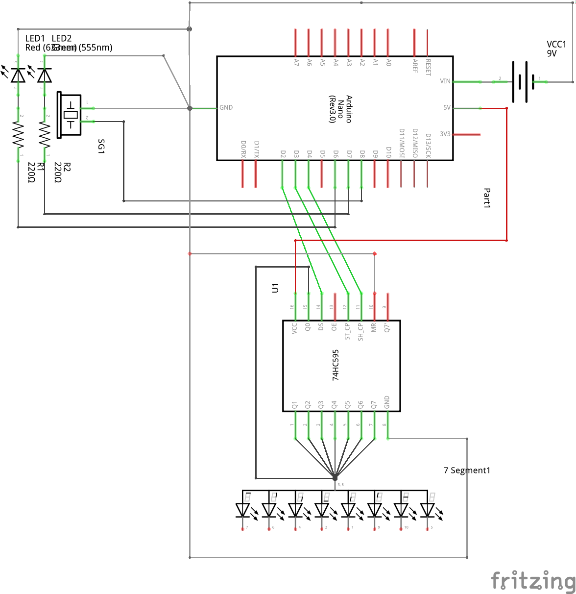
Schematics
Just keep in mind the D10 getting connected to the 5V, will constitute a failure causing the buzzer to beep and counter to count. In the schematic there wasn't a way to show it.
So build up your wires and structure accordingly :)