


Designing a 4‑Bit Combination Lock with XOR & NOR Gates
Designing a 4‑Bit Combination Lock with XOR & NOR Gates
Parts & Materials
- 4001 quad NOR gate (Radio Shack catalog # 276-2401)
- 4070 quad XOR gate (Radio Shack catalog # 900-6906)
- Two, eight-position DIP switches (Radio Shack catalog # 275-1301)
- Two light-emitting diodes (Radio Shack catalog # 276-026 or equivalent)
- Four 1N914 “switching” diodes (Radio Shack catalog # 276-1122)
- Ten 10 kΩ resistors
- Two 470 Ω resistors
- Pushbutton switch, normally open (Radio Shack catalog # 275-1556)
- Two 6 volt batteries
Caution: The 4001 and 4070 ICs are CMOS and highly sensitive to static electricity. Handle with care.
Concept Overview
This experiment demonstrates how XOR gates can serve as bit comparators in a simple 4‑bit combination lock. Two switch assemblies are used: one holds the secret code, the other allows a user to input a candidate code. The lock logic compares the two codes; a green LED indicates a match, while a red LED indicates a mismatch.
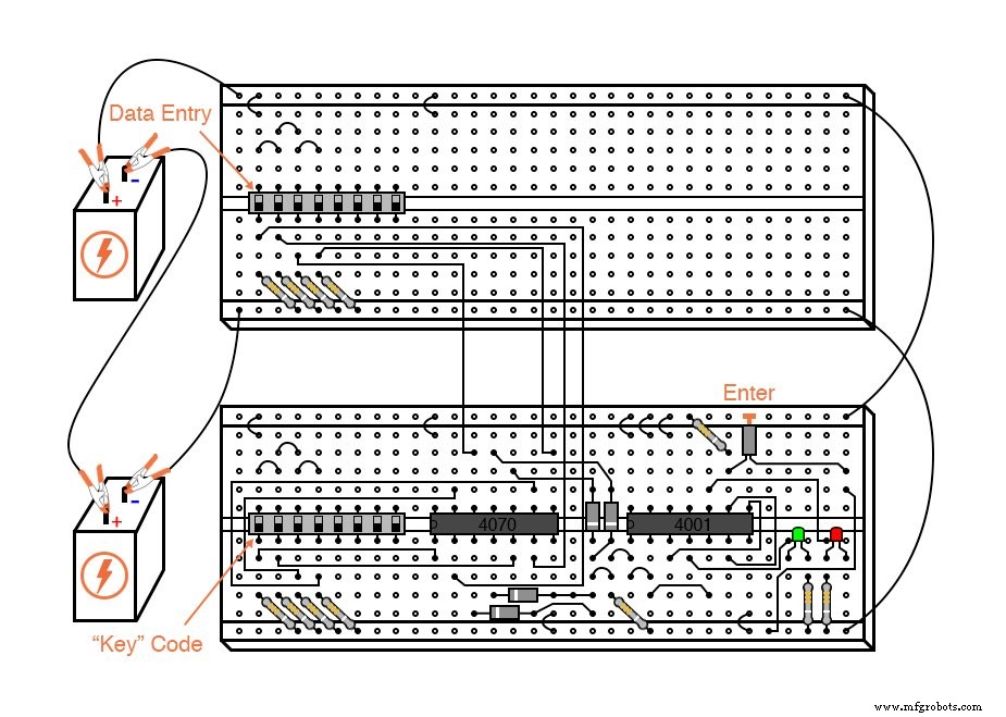
In a real application, the key code assembly would be hidden from view and physically separated from the data‑entry assembly. For educational purposes, the circuit can be built on a single breadboard using one 8‑position DIP switch split into two 4‑bit halves.
Learning Objectives
- Use XOR gates as bit comparators.
- Build basic gate functions with diodes and pull‑up/down resistors.
- Implement NOR gates as controlled inverters.
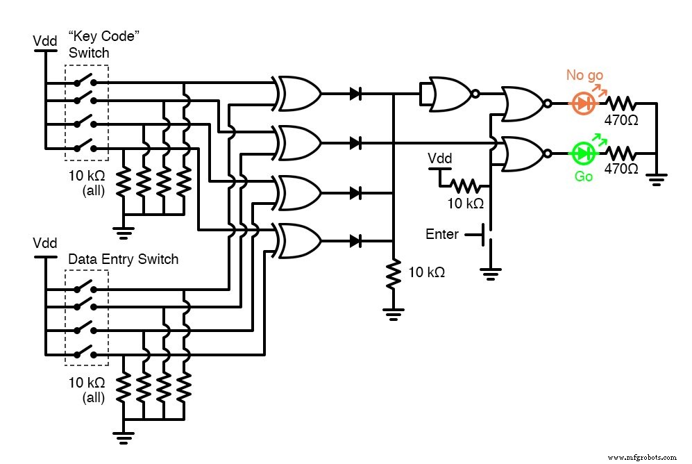
Schematic Diagram
Illustration
Instructions
The circuit uses four XOR gates to compare each bit of two 4‑bit numbers entered via the switches. When the “Enter” pushbutton is pressed, the XOR outputs are routed through a diode network that functions as a 4‑input OR gate. If any XOR output is high—indicating a mismatch—the OR network drives a NOR gate that activates the red “No go” LED. If all XOR outputs are low, the NOR gate allows the green “Go” LED to light.
Because a 4‑bit code has only 16 possible combinations, this lock is simple and illustrative. In a practical security system, the “No go” output would trigger an alarm or deterrent to prevent brute‑force attempts.
When constructing the circuit, keep the key code assembly hidden from the user. In an educational setting, the two 8‑position DIP switches can be placed on separate breadboards, or a single 8‑position switch can be split into two 4‑bit halves.
Note: An XOR gate outputs a high signal only when its two inputs differ. The diode network combines the four XOR outputs into a single logic level that the NOR gate can process. The NOR gate’s output is conditioned by the pushbutton, ensuring LEDs only activate when the user explicitly presses “Enter.”
For enhanced security in a real lock, consider adding a penalty for repeated incorrect attempts—such as a delay or audible alarm—to discourage trial‑and‑error attacks.
Related Worksheet
- CMOS Logic Gates Worksheet
Industrial Technology
- Circuit With a Switch: A Practical Guide to Basic Electrical Circuits
- Commutating Diode Experiment: Suppressing Inductive Kickback with a Neon Lamp
- Combination Lock: Design, Manufacturing, and Historical Evolution
- DIY Frequency Meter – Measure Up to 6.5 MHz with Arduino Nano
- Secure Your PC with an RFID‑Enabled Door Lock – Arduino Relay Project
- Professional Wiring Guide for Combo Switch/Outlet Devices – Diagrams & Installation Tips
- Control a Single Light from Two Locations with 2‑Way Switching: Step‑by‑Step Guide
- How to Wire a Double 3-Way Combination Switch Device: A Complete Installation Guide
- Step‑by‑Step Guide to Wiring a 3‑Way Combo Switch with Grounded Outlet
- Touch Switch Circuits: A Beginner’s Guide to Simple Tactile Sensors