


Build an LED Sequencer with 555 Timer & 4017 Counter – Frequency Division & Debounce
PARTS AND MATERIALS
- 4017 decade counter/divider (Radio Shack catalog # 276-2417)
- 555 timer IC (Radio Shack catalog # 276-1723)
- Ten‑segment bargraph LED (Radio Shack catalog # 276-081)
- One SPST switch
- One 6‑volt battery
- 10 kΩ resistor
- 1 MΩ resistor
- 0.1 µF capacitor (Radio Shack catalog # 272-135 or equivalent)
- Coupling capacitor, 0.047–0.001 µF
- Ten 470 Ω resistors
- Audio detector with headphones
Caution! The 4017 IC is CMOS and therefore sensitive to static electricity.
Any single‑pole, single‑throw switch works; a household light switch is sufficient and widely available.
The audio detector helps you assess signal frequency. If you have an oscilloscope, you can omit it.
CROSS‑REFERENCES
Lessons In Electric Circuits, Volume 4, chapter 3: “Logic Gates”
Lessons In Electric Circuits, Volume 4, chapter 4: “Switches”
Lessons In Electric Circuits, Volume 4, chapter 11: “Counters”
LEARNING OBJECTIVES
- Generate clock pulses with a 555 astable multivibrator.
- Use a 4017 decade counter to produce a one‑of‑ten pulse sequence.
- Employ the 4017 as a frequency divider.
- Measure frequency using a stopwatch and the counter’s output.
- Explain the role of a pulldown resistor.
- Understand switch‑bounce effects on digital circuits.
- Implement 555‑based debounce for a mechanical switch.
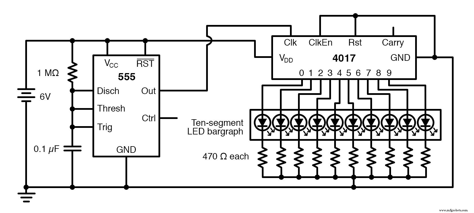
SCHEMATIC DIAGRAM
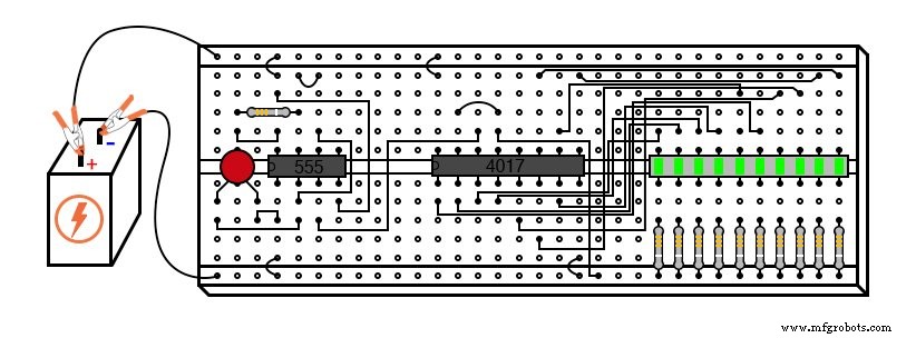
ILLUSTRATION
INSTRUCTIONS
The 4017 IC is a CMOS decade counter with ten output pins. When a low‑to‑high transition occurs on its clock pin (pin 14), the chip advances one step, setting the next output high while the others remain low. With a 555 timer configured as an astable oscillator, the counter cycles through all ten outputs, lighting each LED in turn and then restarting the sequence. Adjusting the 555’s resistor and capacitor values changes the flash rate.
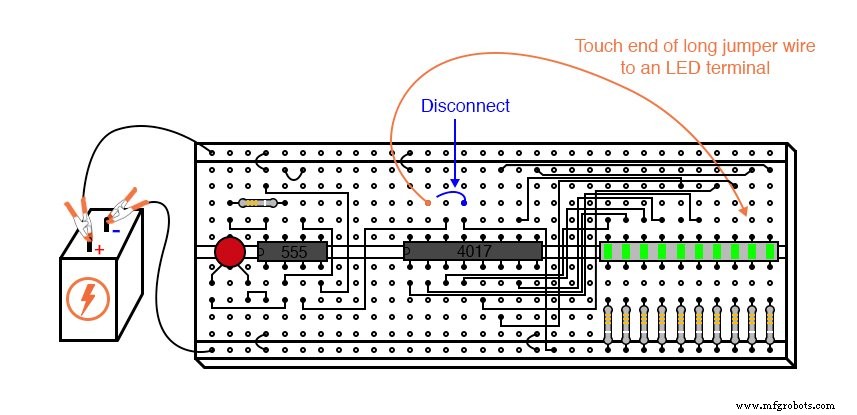
Disconnect the jumper from pin 14 (clock) to pin 3 (output) and hold the free end. Ambient 60‑Hz line noise will drive the counter so that the LEDs blink rapidly, demonstrating the counter’s sensitivity to external high‑frequency signals.
Pin 15 (Reset) and pin 13 (Clock Enable) are tied to ground so the counter runs freely. Pulling Reset high returns the counter to zero (pin 3 high, others low). Pulling Clock Enable high pauses the count. Connecting Reset to one of the output pins shortens the sequence; experiment by moving a jumper from ground to each output and observe which LEDs illuminate.
Images:
Because the 4017 is a frequency divider, a 200‑Hz clock from the 555 produces a 20‑Hz pulse on any output when the full ten‑step sequence is enabled. In general, each output delivers a pulse once per ten clock cycles.
To hear this division, connect a 0.047–0.001 µF coupling capacitor from output 0 (pin 3) to ground and feed it into an audio detector. With Reset grounded, you’ll hear a “click” every time the 0 LED turns on—one‑tenth of the 555’s frequency.
Use a stopwatch to count clicks in one minute. Multiply the count by ten and divide by 60 to obtain the 555’s frequency in Hz. In my build (1 MΩ, 0.1 µF, 13 V supply), 79 clicks per minute yielded 13.17 Hz.
To hear the undivided clock, connect the audio detector to pin 3 of the 555. The resulting buzz is the raw oscillator frequency.
By tying Reset to an intermediate output, you can create division ratios of 1/9, 1/8, …, 1/2. For example, connecting Reset to the sixth LED yields a 1/5 ratio, producing approximately twice the click rate of the 1/10 configuration.
Replace the 1 MΩ timing resistor with a smaller value (e.g., 10 kΩ) to increase the 555’s frequency. Listen to the varied tones as you move the Reset jumper—octaves appear when the division factor is 2, 4, or 8.
Switch‑bounce demonstration: Disconnect the 555 and connect a SPST switch in series with a 10 kΩ pulldown resistor to pin 14. The pulldown ensures a defined low state when the switch opens, preventing floating input and spurious counts. When you toggle the switch, the counter may skip steps due to rapid contact bounce.
To eliminate bounce, use the 555 as a monostable debouncer: connect the switch to the Trigger pin, and use the 555’s output to drive the counter’s clock. Ensure the capacitor’s charge time exceeds the switch’s settling period but is short enough not to miss rapid activations.
With the debounced circuit, each switch press results in a single count, restoring the expected LED sequence.
Industrial Technology
- Using a Transistor as an Electrically Controlled Switch
- Cuckoo Clock: History, Craftsmanship, and Modern Evolution
- Analog-Style LED Persistence‑of‑Vision Clock – DIY Arduino Nano Project
- Arduino Flip Clock with 8×8 LED Matrix – DIY Real‑Time Clock Project
- Create Your Own LED Color Sequencer with Arduino – Easy DIY Tutorial
- Arduino Real-Time Clock LED Clock: Build a Reliable Time Display
- Create a Modern Wooden LED Clock with Arduino Nano and DS3231 RTC
- Mini LED Matrix Clock – Arduino Nano Powered Timepiece
- LED Roulette Circuit Using 555 Timer & CD4017 Counter – Full Diagram & Build Guide
- Build a USB-Powered LED Fan Clock with Arduino Nano – Circuit Diagram & Code