Analog-Style LED Persistence‑of‑Vision Clock – DIY Arduino Nano Project
Components and supplies
Arduino Nano R3
×
1
LED (generic)
×
17
Hall Effect Sensor
×
1
Resistor 100 ohm
×
17
DC motor (generic)
×
1
Boost (Step Up) Switching Regulator, Fixed
×
1
Necessary tools and machines
Soldering iron (generic)
Apps and online services
Arduino IDE
About this project
Persistence of Vision (POV) displays are generally LED displays which ‘show’ images by displaying a section of an image at a given time, in quick rapid succession. The human brain perceives this as display of a continuous image.
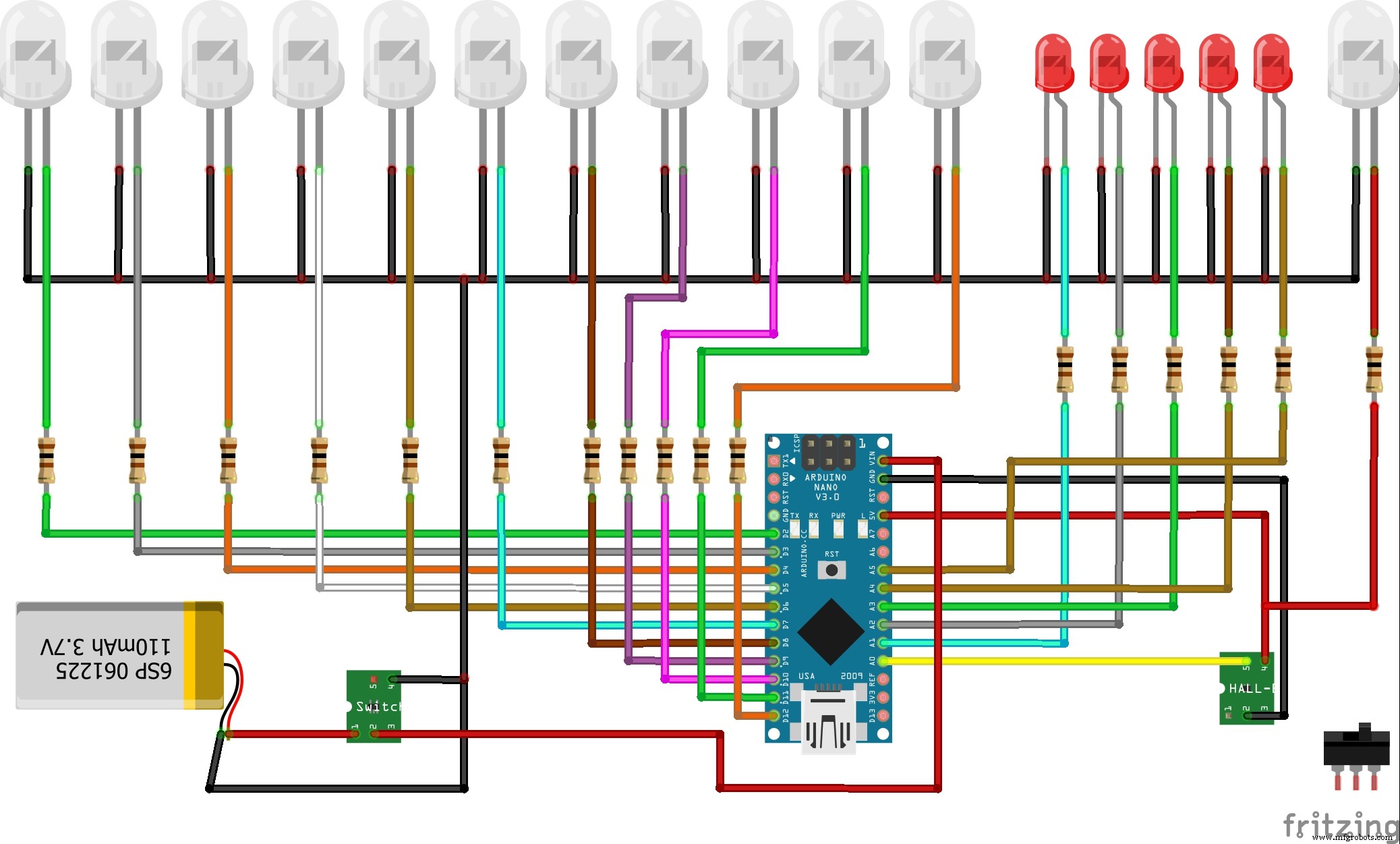
On the "hobby project" website is presented this relatively simple but visually effective analog style face clock. The electronic part contains the Arduino Nano 17 LED diodes and the Hall effect sensor. LED Diode groups d1-d11, d12-d16 and d17 are of different color for better visual effect.The device is powered by a lithium ion battery through a step-up converter.
The most difficult part of the projects for me was mechanical stability. In the first attempt, the battery was set eccentrically and at a higher speed of rotation there was a huge vibration. Then I made a modification and put the battery in the center of rotation.
For rotation I use a 12V electric motor connected to a variable power supply so the speed of rotation of the device can be easy controlled. Depending on the speed of rotation of the device, in the code you need to set the value of "delayMicroseconds" to a determined value.
The presented video is not clear enough, because for this purpose I need a camera with a better frames per second.
Code
code
codeArduino
// hobbyprojects
// ArduinoNanoPropellerLEDAnalogClock20190403A

int LED1 = 2;
int LED2 = 3;
int LED3 = 4;
int LED4 = 5;
int LED5 = 6;
int LED6 = 7;
int LED7 = 8;
int LED8 = 9;
int LED9 = 10;
int LED10 = 11;
int LED11 = 12;
int LED12 = A1;
int LED13 = A2;
int LED14 = A3;
int LED15 = A4;
int LED16 = A5;

int sensorPin = A0;

unsigned int n,ADCvalue,propeller_posn;
unsigned long previousTime = 0;

byte hours = 12;    // set hours
byte minutes = 15;  // set minutes
byte seconds = 00;  // set seconds

int val;

void setup()
{
  pinMode(LED1,OUTPUT);
  pinMode(LED2,OUTPUT);
  pinMode(LED3,OUTPUT);
  pinMode(LED4,OUTPUT);
  pinMode(LED5,OUTPUT);
  pinMode(LED6,OUTPUT);
  pinMode(LED7,OUTPUT);
  pinMode(LED8,OUTPUT);
  pinMode(LED9,OUTPUT);
  pinMode(LED10,OUTPUT);
  pinMode(LED11,OUTPUT);
  pinMode(LED12,OUTPUT);
  pinMode(LED13,OUTPUT);
  pinMode(LED14,OUTPUT);
  pinMode(LED15,OUTPUT);
  pinMode(LED16,OUTPUT);

  pinMode(sensorPin,INPUT_PULLUP);

  if(hours == 12)
  hours = 0;
}

void loop()
{
    val = digitalRead(sensorPin);

    while (val == LOW)
  {
    val = digitalRead(sensorPin);
  }


  if (millis() >= (previousTime))
  {
     previousTime = previousTime + 1000;
     seconds = seconds+1;
     if (seconds == 60)
     {
        seconds = 0;
        minutes = minutes+1;
     }
     if (minutes == 60)
     {
        minutes = 0;
        hours = hours+1;
     }
     if (hours == 12)
     {
        hours = 0;
     }
  }

  propeller_posn=30;
  n=0;

  while(n < 60)
  {

  drawMinuteMarker();

  if ((propeller_posn==0) || (propeller_posn==5) || (propeller_posn==10) || (propeller_posn==15) || (propeller_posn==20) || (propeller_posn==25) || (propeller_posn==30) || (propeller_posn==35) || (propeller_posn==40) || (propeller_posn==45) || (propeller_posn==50) || (propeller_posn==55))
  drawHourMarker();

  if ((propeller_posn==0) || (propeller_posn==15) || (propeller_posn==30) || (propeller_posn==45))
  drawQuarterMarker();

  if((propeller_posn == hours*5) || (( propeller_posn == 0 ) && (hours == 0)))
  drawHoursHand();

  if(propeller_posn == minutes)
  drawMinutesHand();

  if(propeller_posn == seconds)
  drawSecondsHand();

  delayMicroseconds(140);     // for LED pixel width   (change the value according to motor speed. Increase for low speed, decrease for high speed motor)

  displayClear();

  drawInner_Circle();

  delayMicroseconds(600);   // for the gap between LED pixels/minutes markers  (change the value according to motor speed. Increase for low speed, decrease for high speed motor)

  n++;
  propeller_posn++;
  if(propeller_posn == 60)
  propeller_posn=0;
  }

    val = digitalRead(sensorPin);

    while (val == HIGH)
    {
    val = digitalRead(sensorPin);
    }
}

//=========================

void displayClear()
  {
  digitalWrite(LED1,LOW);
  digitalWrite(LED2,LOW);
  digitalWrite(LED3,LOW);
  digitalWrite(LED4,LOW);
  digitalWrite(LED5,LOW);
  digitalWrite(LED6,LOW);
  digitalWrite(LED7,LOW);
  digitalWrite(LED8,LOW);
  digitalWrite(LED9,LOW);
  digitalWrite(LED10,LOW);
  digitalWrite(LED11,LOW);
  digitalWrite(LED12,LOW);
  digitalWrite(LED13,LOW);
  digitalWrite(LED14,LOW);
  digitalWrite(LED15,LOW);
  digitalWrite(LED16,LOW);
  }

  void drawMinuteMarker()
  {
  digitalWrite(LED16,HIGH);
  }

  void drawHourMarker()
  {
  digitalWrite(LED15,HIGH);
  digitalWrite(LED14,HIGH);
  }

  void drawQuarterMarker()
  {
  digitalWrite(LED13,HIGH);
  digitalWrite(LED12,HIGH);
  }

  void drawHoursHand()
  {
  digitalWrite(LED1,HIGH);
  digitalWrite(LED2,HIGH);
  digitalWrite(LED3,HIGH);
  digitalWrite(LED4,HIGH);
  digitalWrite(LED5,HIGH);
  digitalWrite(LED6,HIGH);
  digitalWrite(LED7,HIGH);
  }

  void drawMinutesHand()
  {
  digitalWrite(LED1,HIGH);
  digitalWrite(LED2,HIGH);
  digitalWrite(LED3,HIGH);
  digitalWrite(LED4,HIGH);
  digitalWrite(LED5,HIGH);
  digitalWrite(LED6,HIGH);
  digitalWrite(LED7,HIGH);
  digitalWrite(LED8,HIGH);
  digitalWrite(LED9,HIGH);
  }

  void drawSecondsHand()
  {
  digitalWrite(LED1,HIGH);
  digitalWrite(LED2,HIGH);
  digitalWrite(LED3,HIGH);
  digitalWrite(LED4,HIGH);
  digitalWrite(LED5,HIGH);
  digitalWrite(LED6,HIGH);
  digitalWrite(LED7,HIGH);
  digitalWrite(LED8,HIGH);
  digitalWrite(LED9,HIGH);
  digitalWrite(LED10,HIGH);
  digitalWrite(LED11,HIGH);
  }

  void drawInner_Circle()
  {
  digitalWrite(LED1,HIGH);
  delayMicroseconds(30);
  digitalWrite(LED1,LOW);
  }