


Arduino Nano 4x64 LED Matrix Clock – New Version
Components and supplies
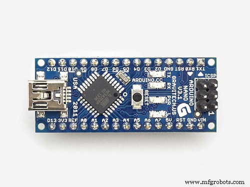 |
| × | 1 | |||
| × | 1 | ||||
 |
| × | 1 | |||
 |
| × | 1 | |||
| × | 1 |
Apps and online services
|
|
About this project
Reading a clock display in a room at several meters requires such a LED matrix display.
Having bought at a good price a 4 cell display, I looked on Hackster for available projects: there are several ones, for Arduino Nano. If you want to see hour, minute and seconds simultaneously: only a few projects work, because you need smaller digits than the widely available ones with 5x7 pixels per digit. An option is to use the MD_Parola library, but the code size is too large for a simple clock. The other tested option was the Max72xxPanel library, but this is too old and calls other libraries. Finally, the project is based on the basic interface library MD_MAX722XX, included in all the others.
The remarks from this site, made me review the hardware aspects and the code.
- There are many libraries called DS3231. I use this one: http://www.rinkydinkelectronics.com/library.php?id=73
Arduino/chipKit library support for the DS3231 I2C Real-Time ClockCopyright (C)2015 Rinky-Dink Electronics, Henning Karlsen. All right reserved
- First: the LED matrix display. There are several models on the market, so it is very likely the display will show weird things after you upload this code. Solution: upload this example from the "MD_MAX72xx_lib.h" library: "MD_MAX72xx_HW_Mapper.ino" and find your hardware model. In my code the model was defined: #define HARDWARE_TYPE MD_MAX72XX::ICSTATION_HW, but this may not work until you set the right model!
- The nice small seconds did not show-up lately? Now (v2), the fonts for these seconds are included in the code, so there is no need to change any other library.
- A long compiling warning list occurred due to Arduino updates. Now, the months are in a two dimensional char array and no longer using a pointer. Any other Warnings come from the DS3231.h library, but can be ignored.
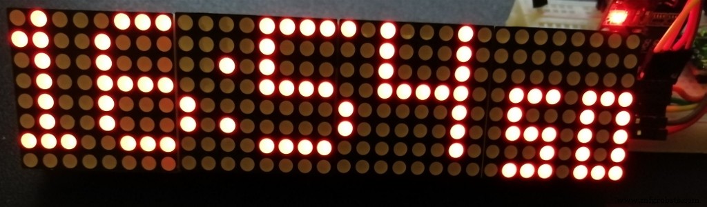
- The blinking dots are now just 2 dots! The accurate seconds are shown, using my 3x5 fonts, after "hh:mm". Moreover, the column dots ":" are blinking almost twice a second, just to show it's alive!
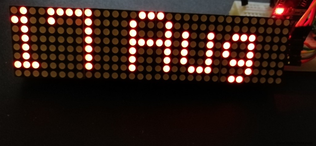
- Answering a request : the time is shown for 53 seconds each minute and during the last 7 seconds are shown the date and temperature.
- The day of the week can also be shown, if you un-comment two lines in the loop(). In this case, you might prefer to reduce the interval of 53 seconds to 51.
- If you prefer the 12 hours format, see one of my older answers.
- The RTC time can be set in the Arduino Serial Monitor by writing in the input area DD/MM/YYYY hh:mm:ss (do not forget the space between) and press Enter/Send. This can be done whenever a USB cable is connected and Serial Monitor is functional (correct COM and baud rate).
The new code use 13558 bytes (44%) and 372 bytes (18%) for variables, so it is a bit shorter!
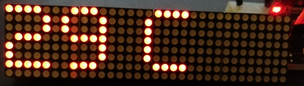
The date is shown as "dd Mon" and room temperature in deg. Celsius (estimated using the RTC internal sensor) is shown on a separate page. The brightness is controlled by a photo-resistor. The code works however, even without light sensor.
Thank you for your interest, shown by the "respect" button!
Code
- OLD version - Arduino Nano Dot Matrix clock
- New version (v2) - Arduino Nano Dot Matrix clock
OLD version - Arduino Nano Dot Matrix clockArduino
Since many libraries changed since the initial release, this code is obsolete. Use the new versionAll connections are described in the code. For small fonts, change a few lines in MD_MAX72xx_font.cpp, as explained in the code./* WARNING: Initial code is now obsolete. Use the new one (vesion 2)
* Arduino Nano DS3231 clock with LED Matrix 4x(8x8) SPI
*
* Arduino Nano 5V logic - 32kB prog. space
* Tools:Board: Arduino Nano; Processor: ATmega328P (Old Bootloader)!!
* LED Matrix 4x(8x8) SPI with connector on the right side (last module)
* https://www.banggood.com/MAX7219-Dot-Matrix-Module-4-in-1-Display-For-Arduino-p-1072083.html?rmmds=myorder&cur_warehouse=CN
*
* CONNECTIONS:
* >> LCD 4x64 -> Arduino Nano: (using Hardware SPI):
* 5V -> 5V pin
* GND -> GND pin
* CLK_PIN -> 13 // or SCK
* DATA_PIN -> 11 // or MOSI
* CS_PIN -> 10 // or SS
*
* >> DS3231 RTC -> Arduino Nano:
* SDA (DAT) -> A4
* SCL (CLK) -> A5
* Inspired by : 1) Arduino Clock by AnthoTRONICS Last edit: March 22,2019
* but without MD_parola because of its large footprint! New getdate function.
* 2) Simplest UNO Digital Clock Ever by plouc68000:
* https://create.arduino.cc/projecthub/plouc68000/simplest-uno-digital-clock-ever-4613aa?ref=user&ref_id=680368&offset=1
* 3) LEDDotMatrixClock.ino by Leonardo Sposina, but here without "Max72xxPanel.h"
* https://github.com/leonardosposina/arduino-led-dot-matrix-clock/blob/master/LEDDotMatrixClock/LEDDotMatrixClock.ino
* Not using Max72xxPanel.h, but small size digits are stll used. Small footprint code here.
* Replace in library MD_MAX72XX/src/MD_MAX72xx_font.cpp :
* 1) #define USE_NEW_FONT 1
* 2) fonts #148 ... 158 must be replaced with 3x5 fonts:
3, 248, 136, 248, // 48 0
3, 144, 248, 128, // 49 1
3, 200, 168, 184, // 50 2
3, 136, 168, 248, // 51 3
3, 112, 72, 224, // 52 4
3, 184, 168, 232, // 53 5
3, 248, 168, 232, // 54 6
3, 8, 232, 24, // 55 7
3, 248, 168, 248, // 56 8
3, 184, 168, 248, // 57 9
1, 80, // 58 :
*
* project: 13790 bytes (44%); variables 361 bytes (17%)
* Author: MVP https://www.hackster.io/M-V-P
*/
#include <SPI.h>
#include "DS3231.h"
#include "MD_MAX72xx_lib.h"
//#include "Font_Data.h"
DS3231 rtc(SDA, SCL); // Real time clock
const byte LDR_PIN = A2; // LDR Sensor pin
#define MAX_DEVICES 4
// Define pins
#define CLK_PIN 13 // or SCK
#define DATA_PIN 11 // or MOSI
#define CS_PIN 10 // or SS
#define HARDWARE_TYPE MD_MAX72XX::ICSTATION_HW
#define USE_NEW_FONT 1
#define BUF_SIZE 20 // text buffer size
#define CHAR_SPACING 1 // pixels between characters
char buf[BUF_SIZE], secs[4];
uint8_t dots;
// SPI hardware interface
// Max72xxPanel matrix = Max72xxPanel(CS_PIN, H_DISPLAYS, V_DISPLAYS);
MD_MAX72XX matrix = MD_MAX72XX(HARDWARE_TYPE, CS_PIN, MAX_DEVICES);
const byte WAIT = 100;
const byte SPACER = 1;
byte FONT_WIDTH;
bool timeset=false;
void adjustClock(String data) {
byte _day = data.substring(0,2).toInt();
byte _month = data.substring(3,5).toInt();
int _year = data.substring(6,10).toInt();
byte _hour = data.substring(11,13).toInt();
byte _min = data.substring(14,16).toInt();
byte _sec = data.substring(17,19).toInt();
rtc.setTime(_hour, _min, _sec);
rtc.setDate(_day, _month, _year);
Serial.println(F(">> Datetime successfully set!"));
timeset=true;
}
byte ledintensitySelect(int light) {
byte _value = 0;
if (light >= 0 && light <= 127) {
_value = 12;
} else if (light >= 128 && light <= 319) {
_value = 3;
} else if (light >= 320 && light <= 512) {
_value = 0;
}
return _value;
};
void printText(uint8_t modStart, uint8_t modEnd, char *pMsg)
// Print the text string to the LED matrix modules specified.
// Message area is padded with blank columns after printing.
{
uint8_t state = 0;
uint8_t curLen;
uint16_t showLen;
uint8_t cBuf[FONT_WIDTH];
int16_t col = ((modEnd + 1) * COL_SIZE) - 1;
matrix.control(modStart, modEnd, MD_MAX72XX::UPDATE, MD_MAX72XX::OFF);
do // finite state machine to print the characters in the space available
{
switch(state)
{
case 0: // Load the next character from the font table
// if we reached end of message, reset the message pointer
if (*pMsg == '\0')
{
showLen = col - (modEnd * COL_SIZE); // padding characters
state = 2;
break;
}
// retrieve the next character form the font file
showLen = matrix.getChar(*pMsg++, sizeof(cBuf)/sizeof(cBuf[0]), cBuf);
curLen = 0;
state++;
// !! deliberately fall through to next state to start displaying
case 1: // display the next part of the character
matrix.setColumn(col--, cBuf[curLen++]);
// done with font character, now display the space between chars
if (curLen == showLen)
{
showLen = CHAR_SPACING;
state = 2;
}
break;
case 2: // initialize state for displaying empty columns
curLen = 0;
state++;
// fall through
case 3: // display inter-character spacing or end of message padding (blank columns)
matrix.setColumn(col--, 0);
curLen++;
if (curLen == showLen)
state = 0;
break;
default:
col = -1; // this definitely ends the do loop
}
} while (col >= (modStart * COL_SIZE));
matrix.control(modStart, modEnd, MD_MAX72XX::UPDATE, MD_MAX72XX::ON);
}
void setup() {
pinMode(LDR_PIN, INPUT_PULLUP);
Serial.begin(9600);
Serial.println(F(">> Arduino 32x8 LED Dot Matrix Clock!"));
Serial.println(F(">> Use <dd/mm/yyyy hh:mm:ss> format to set clock's date and hour!"));
rtc.begin();
matrix.begin();
matrix.clear();
FONT_WIDTH= 5 + SPACER; // The font width is 5 pixels
matrix.control(MD_MAX72XX::INTENSITY, 2);; // Use a value between 0 and 15 for brightness
}
void getDate()
// Date Setup: Code for reading clock date
{ char* months[]={"Jan","Feb","Mar","Apr","May","Jun","Jul","Aug","Sep","Oct","Nov","Dec"};
String dts = rtc.getDateStr(); // Get dd/mm/yyyy string
String dds=dts.substring(0,2); // Extract date
String mms=dts.substring(3,5); // Extract month
int mm=mms.toInt(); // Convert to month number
dds.concat(" ");
dds.concat(String(months[mm-1])); // Rebuild date string as "dd Mmm"
dds.toCharArray(buf,sizeof(buf)); // return buffer
}
void getHour()
// Date Setup: Code for reading clock date
{ String dts = rtc.getTimeStr(); // Get hh:mm:ss string
String hhs=dts.substring(0,2); // Extract hour
int hh=hhs.toInt(); // Convert to number
if (hh < 10) dots=7;
if(hh > 19 && hh < 24)
dots=13;
if ((hh > 9 && hh < 20) || (hh == 21))
dots=11;
if (hh == 1) dots=5;
if (hh == 11) dots=10;
//String outmsg=dts.substring(0,5); // Extract hh:mm (optional)
String outmsg=String(hh); // Extract h if h<10
outmsg.concat(":"); // add :
outmsg.concat(dts.substring(3,5)); // add mm
outmsg.toCharArray(buf,BUF_SIZE);
}
void showsec()
{
String dts = rtc.getTimeStr(); // Get hh:mm:ss string
String scs1=dts.substring(6,7);
String scs2=dts.substring(7);
char sc1=148+scs1.toInt(); // Convert to index of char
char sc2=148+scs2.toInt(); // Convert to index of char
matrix.setChar(6,sc1);
matrix.setChar(2,sc2);
}
void loop() {
byte ledIntensity = ledintensitySelect(analogRead(LDR_PIN));
matrix.control(MD_MAX72XX::INTENSITY, ledIntensity);; // Use a value between 0 and 15 for brightness
// Show hh:mm from buf
getHour();
printText(0,MAX_DEVICES-1,buf);
delay(WAIT);
// Blinking two dots:
for (uint8_t i=0; i<8; i++){
matrix.setColumn(MAX_DEVICES*8-dots,36);
showsec();
delay(250);
matrix.setColumn(MAX_DEVICES*8-dots,0);
showsec();
delay(250);
}
// Exit by scrolling upwards:
for (uint8_t i=0; i<8; i++){
matrix.transform(MD_MAX72XX::TSU); delay(2*WAIT);
delay(WAIT);
}
getDate();
printText(0,MAX_DEVICES-1,buf);
delay(20*WAIT);
int temp = rtc.getTemp();
temp=temp-1; // Offset -1 C
String outmsg=String(temp);
outmsg.concat(" C");
outmsg.toCharArray(buf,BUF_SIZE);
printText(0,MAX_DEVICES-1,buf);
delay(20*WAIT);
// Time setting in RTC:
if (Serial.available() > 0 && timeset==false) {
adjustClock(Serial.readString());
}
}
New version (v2) - Arduino Nano Dot Matrix clockArduino
Updated in accordance with new libraries./* Arduino Nano DS3231 clock with LED Matrix 4x(8x8) SPI
* Version 2 - updated 15/05/2-21
* Arduino Nano 5V logic - 32kB prog. space
* Tools:Board: Arduino Nano; Processor: ATmega328P (Old Bootloader)!!
* LED Matrix 4x(8x8) SPI with connector on the right side (last module)
* https://www.banggood.com/MAX7219-Dot-Matrix-Module-4-in-1-Display-For-Arduino-p-1072083.html?rmmds=myorder&cur_warehouse=CN
*
* CONNECTIONS:
* >> LCD 4x64 -> Arduino Nano: (using Hardware SPI):
* 5V -> 5V pin
* GND -> GND pin
* CLK_PIN -> 13 // or SCK
* DATA_PIN -> 11 // or MOSI
* CS_PIN -> 10 // or SS
*
* >> DS3231 RTC -> Arduino Nano:
* SDA (DAT) -> A4
* SCL (CLK) -> A5
* Inspired by : 1) Arduino Clock by AnthoTRONICS Last edit: March 22,2019
* but without MD_parola because of its large footprint! New getdate function.
* 2) Simplest UNO Digital Clock Ever by plouc68000:
* https://create.arduino.cc/projecthub/plouc68000/simplest-uno-digital-clock-ever-4613aa?ref=user&ref_id=680368&offset=1
* 3) LEDDotMatrixClock.ino by Leonardo Sposina, but here without "Max72xxPanel.h"
* https://github.com/leonardosposina/arduino-led-dot-matrix-clock/blob/master/LEDDotMatrixClock/LEDDotMatrixClock.ino
* Not using Max72xxPanel.h, but small size digits are stll used. Small footprint code here.
*
* project: 113558 bytes (44%); variables 372 bytes (17%)
* Author: MVP https://www.hackster.io/M-V-P
*/
#include <SPI.h>
#include "DS3231.h"
#include "MD_MAX72xx_lib.h"
//#include "Font_Data.h"
DS3231 rtc(SDA, SCL); // Real time clock
const byte LDR_PIN = A2; // LDR Sensor pin
#define MAX_DEVICES 4
// Define pins
#define CLK_PIN 13 // or SCK
#define DATA_PIN 11 // or MOSI
#define CS_PIN 10 // or SS
// Define below your LED matrix hardware model:
//#define HARDWARE_TYPE MD_MAX72XX::ICSTATION_HW
#define HARDWARE_TYPE MD_MAX72XX::FC16_HW
#define USE_NEW_FONT 1
#define BUF_SIZE 20 // text buffer size
#define CHAR_SPACING 1 // pixels between characters
char buf[BUF_SIZE], secs[4];
uint8_t hh, mm, ss, dots;
// Definition of the small fonts:
uint8_t Font3x5 [ 10 ][ 3 ]={
{ 248, 136, 248}, // 48 0
{144, 248, 128}, // 49 1
{200, 168, 184}, // 50 2
{136, 168, 248}, // 51 3
{112, 72, 224}, // 52 4
{184, 168, 232}, // 53 5
{248, 168, 232}, // 54 6
{8, 232, 24}, // 55 7
{248, 168, 248}, // 56 8
{184, 168, 248}}; // 57 9
char months[12][4]= {"Jan","Feb","Mar","Apr","May","Jun","Jul","Aug","Sep","Oct","Nov","Dec"};
char* wday;
// SPI hardware interface
// Max72xxPanel matrix = Max72xxPanel(CS_PIN, H_DISPLAYS, V_DISPLAYS);
MD_MAX72XX matrix = MD_MAX72XX(HARDWARE_TYPE, CS_PIN, MAX_DEVICES);
const byte WAIT = 100;
const byte SPACER = 1;
byte FONT_WIDTH;
bool timeset=false;
void adjustClock(String data) {
byte _day = data.substring(0,2).toInt();
byte _month = data.substring(3,5).toInt();
int _year = data.substring(6,10).toInt();
byte _hour = data.substring(11,13).toInt();
byte _min = data.substring(14,16).toInt();
byte _sec = data.substring(17,19).toInt();
rtc.setTime(_hour, _min, _sec);
rtc.setDate(_day, _month, _year);
Serial.println(F(">> Datetime successfully set!"));
timeset=true;
}
byte ledintensitySelect(int light) {
byte _value = 0;
if (light >= 0 && light <= 127) {
_value = 12;
} else if (light >= 128 && light <= 319) {
_value = 3;
} else if (light >= 320 && light <= 512) {
_value = 0;
}
return _value;
};
void printText(uint8_t modStart, uint8_t modEnd, char *pMsg)
// Print the text string to the LED matrix modules specified.
// Message area is padded with blank columns after printing.
{
uint8_t state = 0;
uint8_t curLen;
uint16_t showLen;
uint8_t cBuf[FONT_WIDTH];
int16_t col = ((modEnd + 1) * COL_SIZE) - 1;
matrix.control(modStart, modEnd, MD_MAX72XX::UPDATE, MD_MAX72XX::OFF);
do // finite state machine to print the characters in the space available
{
switch(state)
{
case 0: // Load the next character from the font table
// if we reached end of message, reset the message pointer
if (*pMsg == '\0')
{
showLen = col - (modEnd * COL_SIZE); // padding characters
state = 2;
break;
}
// retrieve the next character form the font file
showLen = matrix.getChar(*pMsg++, sizeof(cBuf)/sizeof(cBuf[0]), cBuf);
curLen = 0;
state++;
// !! deliberately fall through to next state to start displaying
case 1: // display the next part of the character
matrix.setColumn(col--, cBuf[curLen++]);
// done with font character, now display the space between chars
if (curLen == showLen)
{
showLen = CHAR_SPACING;
state = 2;
}
break;
case 2: // initialize state for displaying empty columns
curLen = 0;
state++;
// fall through
case 3: // display inter-character spacing or end of message padding (blank columns)
matrix.setColumn(col--, 0);
curLen++;
if (curLen == showLen)
state = 0;
break;
default:
col = -1; // this definitely ends the do loop
}
} while (col >= (modStart * COL_SIZE));
matrix.control(modStart, modEnd, MD_MAX72XX::UPDATE, MD_MAX72XX::ON);
}
void setup() {
pinMode(LDR_PIN, INPUT_PULLUP);
Serial.begin(9600);
Serial.println(F(">> Arduino 32x8 LED Dot Matrix Clock!"));
Serial.println(F(">> Use <dd/mm/yyyy hh:mm:ss> format to set clock's date and hour!"));
rtc.begin();
matrix.begin();
matrix.clear();
FONT_WIDTH= 5 + SPACER; // The font width is 5 pixels
matrix.control(MD_MAX72XX::INTENSITY, 2);; // Use a value between 0 and 15 for brightness
rtc.setDOW(); // Required for a new RTC
}
void getDate()
// Date Setup: Code for reading clock date
{
String dts = rtc.getDateStr(); // Get dd/mm/yyyy string
String dds=dts.substring(0,2); // Extract date
String mms=dts.substring(3,5); // Extract month
int mm=mms.toInt(); // Convert to month number
dds.concat(" ");
dds.concat(String(months[mm-1])); // Rebuild date string as "dd Mmm"
dds.toCharArray(buf,sizeof(buf)); // return buffer
wday = rtc.getDOWStr(2);
}
void getHour()
// Date Setup: Code for reading clock date
{ String dts = rtc.getTimeStr(); // Get hh:mm:ss string
String hhs=dts.substring(0,2); // Extract hour
String mms=dts.substring(3,5); // Extract minutes
hh=hhs.toInt(); // Convert to number
mm=mms.toInt(); // Convert to number mm
ss=(dts.substring(6,8)).toInt(); // Extract seconds as number
if (hh >= 0 && hh < 10) dots=7;
if (hh > 9 && hh < 20) dots=11;
if (hh > 19 && hh < 25) dots=13;
if (hh%10 == 1) dots-=2;
//String outmsg=dts.substring(0,5); // Extract hh:mm (optional)
String outmsg=String(hh); // Extract h if h<10
// outmsg.concat(":"); // add : but on 2 columns!!
outmsg.concat(char(124)); // add 1 full column between numbers
outmsg.concat(dts.substring(3,5)); // add mm
outmsg.toCharArray(buf,BUF_SIZE);
}
// New version of function, using the small embedded fonts
void showsec(uint8_t secs)
{ uint8_t secs1=secs%10;
uint8_t secs2=secs/10;
for (uint8_t k=0; k<3; k++){
matrix.setColumn(MAX_DEVICES*8-26-k,Font3x5 [secs2][k]);
matrix.setColumn(MAX_DEVICES*8-30-k,Font3x5 [secs1][k]);
}
}
void loop() {
byte ledIntensity = ledintensitySelect(analogRead(LDR_PIN));
matrix.control(MD_MAX72XX::INTENSITY, ledIntensity);; // Use a value between 0 and 15 for brightness
getHour(); // Read time from RTC
printText(0,MAX_DEVICES-1,buf); // Show hh|mm from buf
matrix.setColumn(MAX_DEVICES*8-dots,0); // Clear the |
unsigned long inst =millis(); // mark this moment
while (ss < 53){ // First 53 seconds of each minute show time
while (millis() - inst > 1000){
inst =millis();
ss++; // Increase seconds
showsec(ss); // Show seconds
for (uint8_t i = 0; i < 2; i++){
matrix.setColumn(MAX_DEVICES*8-dots,36); // Blinking two dots:
delay(240);
matrix.setColumn(MAX_DEVICES*8-dots,0);
delay(240);
}
}
}
// Then "time" is scrolling upwards:
for (uint8_t i=0; i<8; i++){
matrix.transform(MD_MAX72XX::TSU);
delay(3*WAIT);
}
// Write the current date:
getDate();
printText(0,MAX_DEVICES-1,buf);
delay(20*WAIT);
// Write the week day (if uncommented):
//printText(0,MAX_DEVICES-1,wday);
//delay(20*WAIT);
// Write the estimated room temperature from the RTC sensor
int temp = rtc.getTemp();
temp=temp-1; // Offset -1 C
String outmsg=String(temp);
outmsg.concat(" C");
outmsg.toCharArray(buf,BUF_SIZE);
printText(0,MAX_DEVICES-1,buf);
delay(20*WAIT);
// Time setting in RTC if Serial monitor is activated in Arduino IDE:
if (Serial.available() > 0 && timeset==false) {
adjustClock(Serial.readString());
}
}
Schematics
Inspired by Leonardo Sposina,but #define CS_PIN(Matrix)<--> 10(Nano)
The schematics is ALMOST the same for all Matrix projects. Here the photo-resistor is original. As mentioned in the code: #define CS_PIN(Matrix)<--> 10(Nano) https://github.com/leonardosposina/arduino-led-dot-matrix-clockManufacturing process
- Arduino Temperature Monitor & Real-Time Clock Using a 3.2” TFT Display
- Control an LED via Bluetooth with Arduino – Simple DIY Guide
- Interactive LED Matrix Door Display with PIR Motion Sensor – Arduino Holiday Greeting
- Arduino Flip Clock with 8×8 LED Matrix – DIY Real‑Time Clock Project
- Mastering an 8×8 LED Matrix with Arduino Uno: A Step‑by‑Step Guide
- Real-Time Arduino Weather Clock: OLED Display for Time, Date & Temperature
- Build a Credit‑Card‑Sized Arduboy Clone with Arduino Nano & I2C OLED
- High-Precision LED Matrix Clock with DS3231 RTC, BME280 Weather, BH1750 Light Sensor & ESP01 NTP Connectivity
- Build a 7‑Segment Clock with Arduino Nano, DS3231 RTC, and LDR Auto‑Brightness
- Mini LED Matrix Clock – Arduino Nano Powered Timepiece