


Build an Ultrasonic Map-Maker with Arduino Yun – A Step-by-Step Guide
Components and supplies
 |
| × | 1 | |||
| × | 1 | ||||
| × | 1 | ||||
 |
| × | 10 |
Apps and online services
 |
| |||
 |
|
About this project
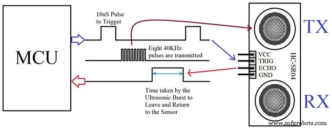
Step 1 : TheoryIn this project, we are using an ultrasonic Distance sensor. It generates sound waves beyond the scope of human hearing and measures distance by calculating the time required by these waves to hit an obstacle and travel back. This is similar to the principle used by bats and cruise ships.
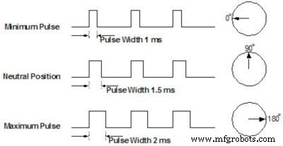
Another component that we are going to use is a servo motor. It differs from the usual DC motor in that it can turn very precisely to a given angular position and hold its state there. When a servo motor is given pulses of a specific duration, it moves to the corresponding angular position.
We will be using both these components to get a 180 degree field of view for our robot.
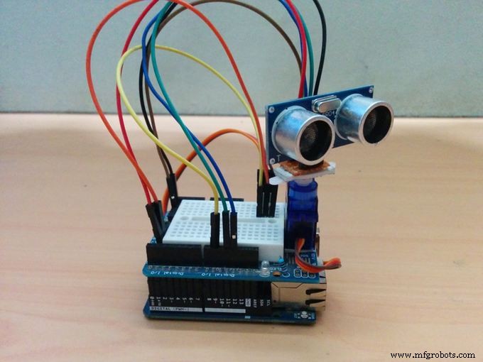
Step 2 : Collecting MaterialsThis project uses the following hardware
- Arduino Uno/Yun (Please note that any Arduino footprint board can be used in place of the Uno or Yun)
- Arduino Prototyping Shield
- An HC-04 Ultrasonic Sensor
- A servo motor (I've used the Tower Pro SG90 because its very compact)
- On the software side we are using the following programs
- The Arduino IDE to upload control code to the Arduino to rotate the servo and get distance data from the ultrasonic sensor and also push it to the serial port.
- Mathworks MatLab to receive data from the serial line, process it and visualize it to a graph.
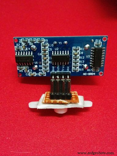
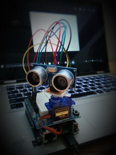
Using a small piece of general purpose PCB, make a small header for the HC-04, and attach it to a servo horn using a piece of double sided tape.
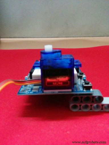
This step is optional, but to make the system more compact, I've attached the servo to the jutting part of the protoboard shield using double sided tape as well.
The final result should look like Wall-E's abdomen.
Step 4 : The Arduino CodeThe Arduino code controls the motion of the servo motor, and when the readings from the ultrasonic sensor are captured and how frequently. It also pushes the sensor data to the serial port.
- Import libraries
- Initialize variables and pins.
- Initialize servo object
- Initialize serial communication
- Wait for 3 seconds
- Initialize counters to 0
- Rotate servo by 1 degree
- Get ultrasonic sensor data 10 times (set by default)
- Average the data
- Send the average to serial port
- Return to step 7
The MatLab code deals more with data than the actual control of the board, so all the sensor data is pushed over serial to the PC, where it is read by MatLab.
Now, the data that we receive from the Arduino tells us two things. The degree of rotation of the servo and the distance of an obstacle in that direction. Hence, the data that we have at this point is in the Polar coordinate system. For it to make sense to human eyes when visualized, it must be converted to the Cartesian or X-Y coordinate system.
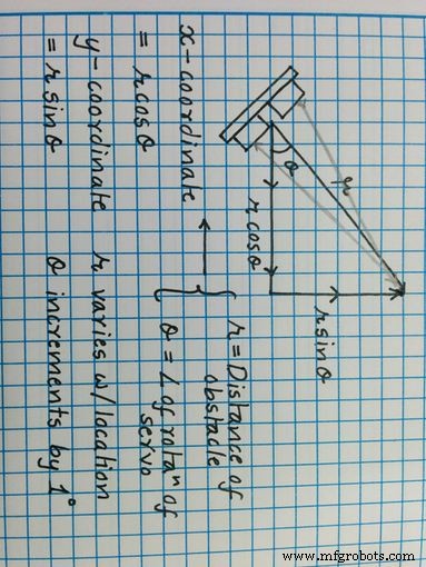
So the MatLab code does just this. It gets data serially from the COM port, saves it into a matrix with the angle of rotation, and then converts it into Cartesian coordinates with the formula given above.
Once it's done, it gives an output by plotting the points on a graph. I placed the board in the box, and I got the following result.
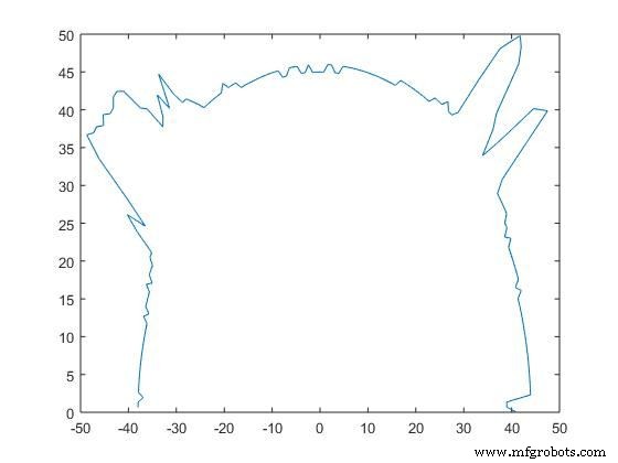
Step 6 : Conclusion
Although the system isn't perfect, it gets the job done. It can get a rough estimate of the box width and length and sends the data accurately.
The only errors that I can see at the moment are due to the shaking of the sensor while the servo is moving and faulty readings from the sensor itself.
Apart from this, the system works fine and can be used for depth perception experiments as well as basic computer vision projects.
Code
- matlab_code_to_run_on_pc.m
- Arduino Code
matlab_code_to_run_on_pc.mMATLAB
MatLab code to be compiled and executed on PCtheta = 0:(pi/180):pi;
s = serial('COM10');
s.BaudRate=9600
fopen(s)
i = 0;
inc = 1;
while i<180
A = fgets(s);
num(i+1) = str2num(A);
i = i+1;
end
fclose(s)
j = 1
while j<181
tab(j,1) = (j-1)*inc
tab(j,2) = num(j)
tab(j,3) = num(j)*cosd((j-1)*inc)
tab(j,4) = num(j)*sind((j-1)*inc)
j = j+1
end
%figure
%polar(theta,num)
plot(tab(:,3),tab(:,4))
Arduino CodeArduino
Arduino Code to be uploaded to Arduino Yun#include <Servo.h>
#include <NewPing.h>
#define TRIGGER_PIN 12
#define ECHO_PIN 11
#define MAX_DISTANCE 200
NewPing sonar(TRIGGER_PIN, ECHO_PIN, MAX_DISTANCE);
Servo myservo;
int pos = 0;
int it = 10;
void setup() {
myservo.attach(9);
Serial.begin(9600);
delay(3000);
}
void loop() {
int i = 0;
int t = 0;
int a = 0;
for (i = 0; i < 180; i ++)
{
unsigned int uS = sonar.ping();
myservo.write(i);
delay(20);
for (t = 0; t < it; t++)
{
uS = sonar.ping();
a = uS/US_ROUNDTRIP_CM + a;
delay(30);
}
a = a / (it-1);
t = 0;
Serial.println(a);
a = 0;
}
}
Schematics
Fritzing file for servo and Ultrasonic sensor connectionsYunConfig.fzzManufacturing process
- Arduino Uno-Based Human Detection Robot: Step‑by‑Step Sensor Integration
- Build an Ultrasonic Levitation Device with Arduino – Step‑by‑Step Guide
- FlickMote: Gesture‑Controlled IR Remote for Smart Home
- Build an Android‑Controlled Remote Vehicle with Raspberry Pi Motor Shield
- Build a Smart IoT Jar with ESP8266, Arduino & Ultrasonic Sensor – Real‑Time Monitoring
- Build a 4-Wheel Arduino Robot Controlled via Dabble App
- Arduino Web-Driven XY Plotter with Stepper Motor Controller
- Master DC & Servo Motor Control with Arduino – Step-by-Step Tutorial
- Precise Ultrasonic Distance Sensing with Arduino – Step‑by‑Step Guide
- Connecting an L293D Motor Driver to a DC Motor with Arduino – Step‑by‑Step Guide