


Build a 48x8 Scrolling LED Matrix with Arduino – Step-by-Step Guide
Components and supplies
 |
| × | 1 | |||
| × | 7 | ||||
 |
| × | 56 | |||
 |
| × | 2 | |||
 |
| × | 21 | |||
| × | 4 | ||||
| × | 6 | ||||
| × | 1 |
Necessary tools and machines
 |
| |||
 |
| |||
 |
|
Apps and online services
 |
|
About this project
Hello all!
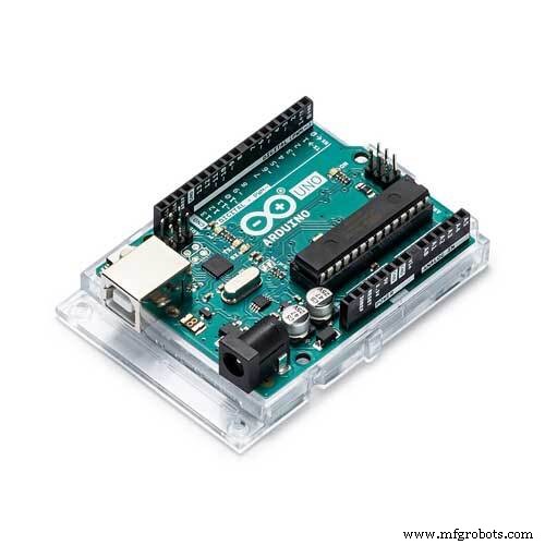
This project is about making a 48x8 Programmable Scrolling LED Matrix using an Arduino UNO and 74HC595 shift registers.
This was my first project with an Arduino development board. It was a challenge given to me by my teacher to try to build one. So at that time of accepting this challenge, i didn't even knew how to blink an LED using an arduino. So, i think even a beginner can do this with a little bit of patience and understanding. I found the circuit diagram online and that was my only reference to build this project. I started off with a little research about shift registers and multiplexing in arduino.
The Circuit
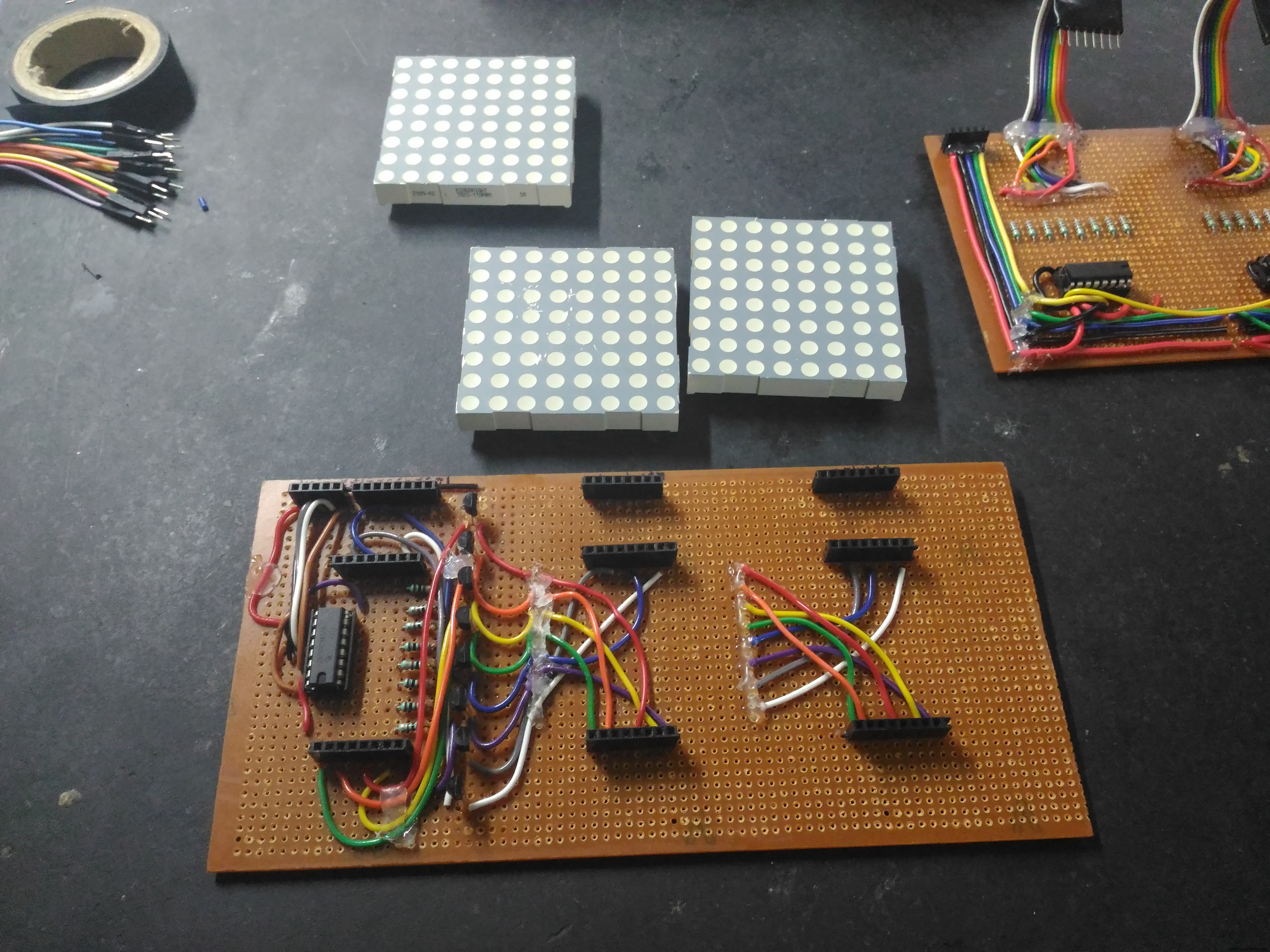
Gathering Components
I gathered all the components from different sources. I got this 5mm 8x8 common cathode LED matrix display from an online website.
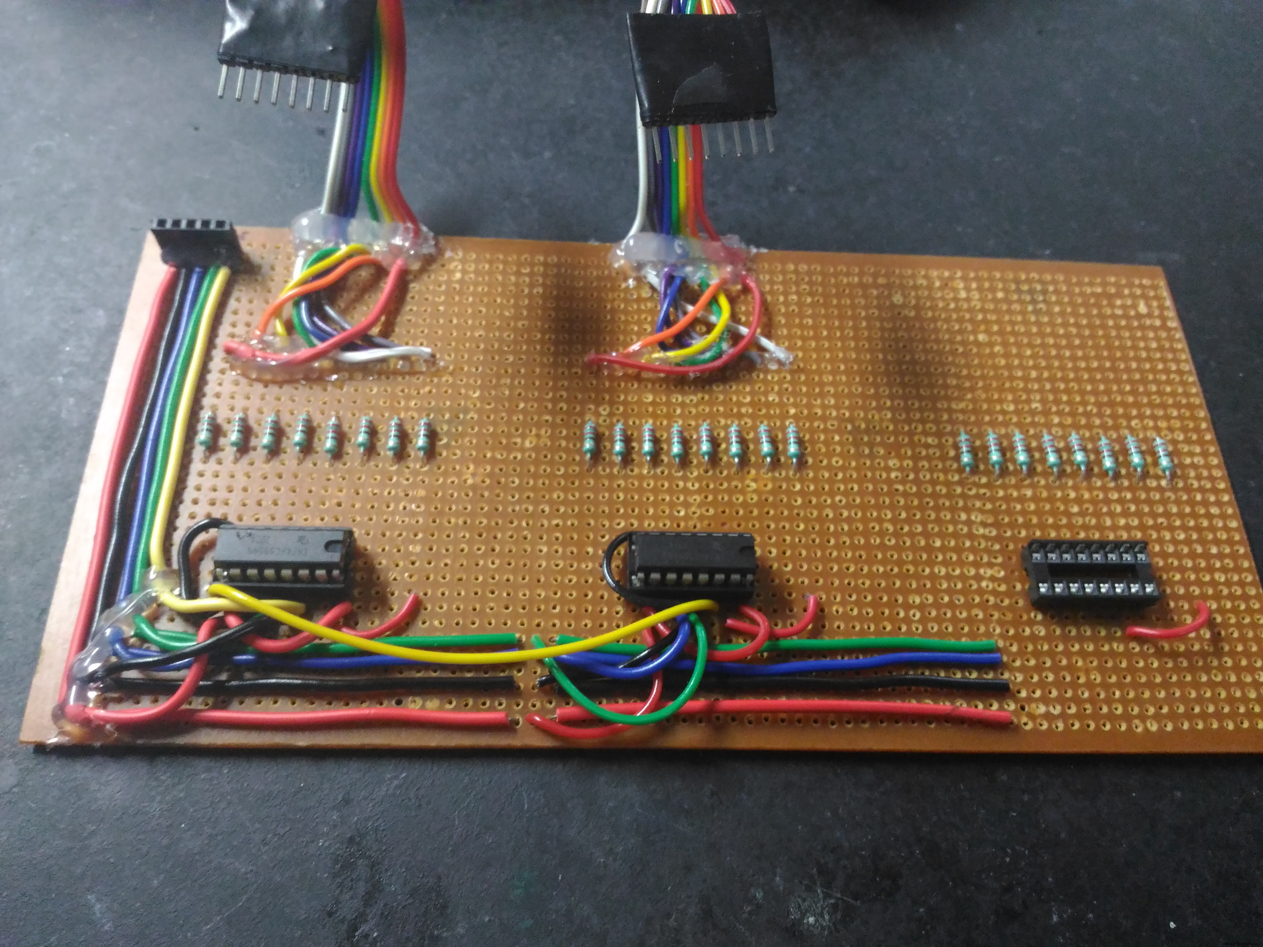
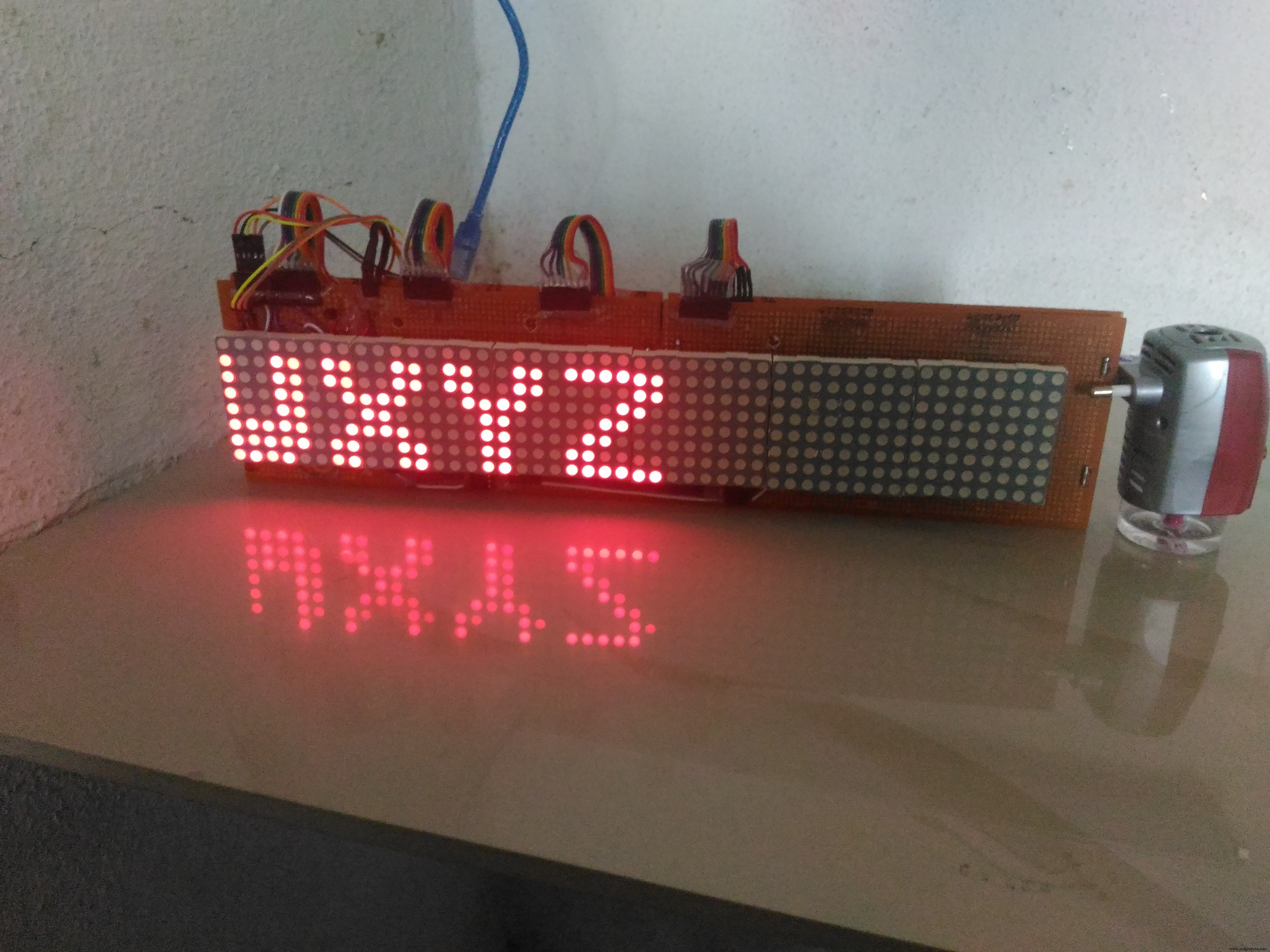
Building the Prototype
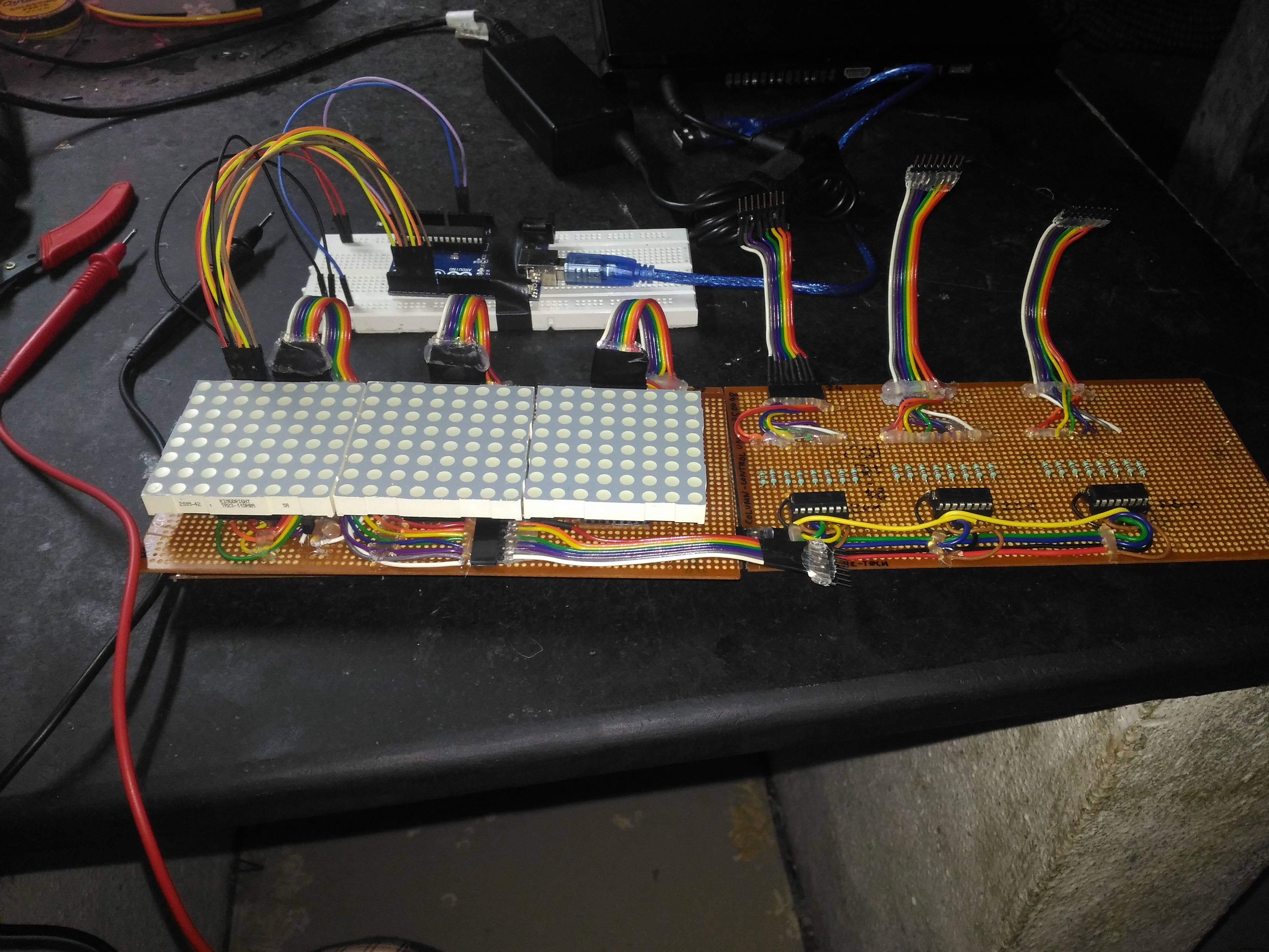
It's shown in the circuit that a single shift register is used to control the 8 rows and for controlling the columns, we use one shift register for each 8 columns.
So if you are able to make a simple 8x8 matrix, you can simply just replicate the portion of the circuit for the column control and extend the matrix to any number of columns. You just need to add one 74hc595 for every 8 columns ( one 8x8 module) you add in to the circuit. Keeping that in mind, i made my 8x8 prototype.
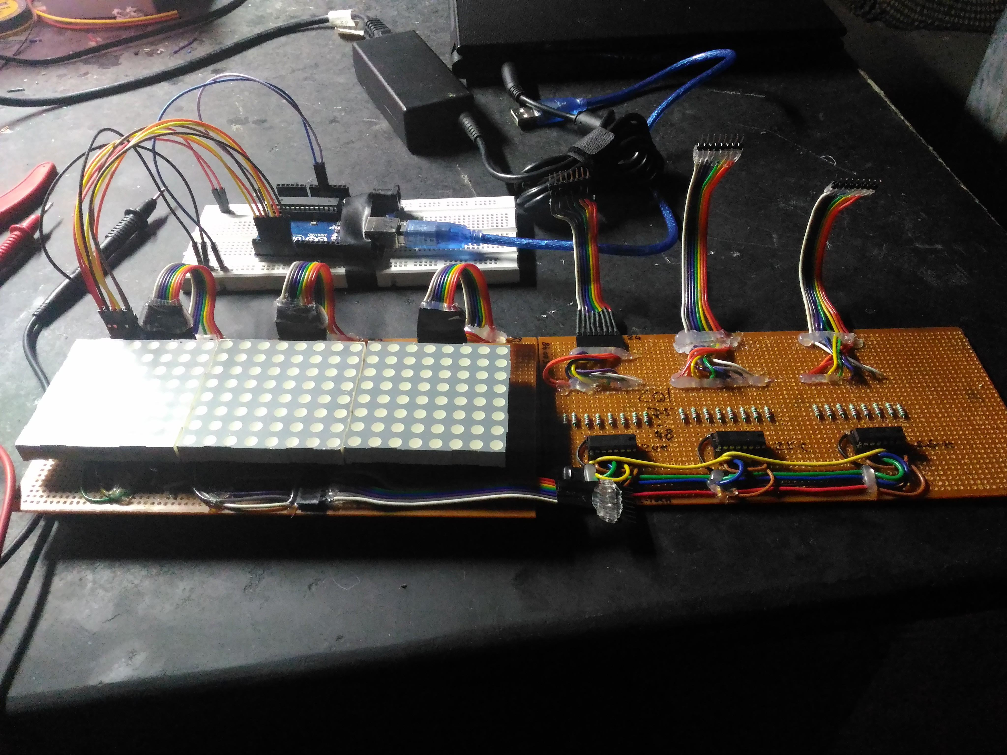
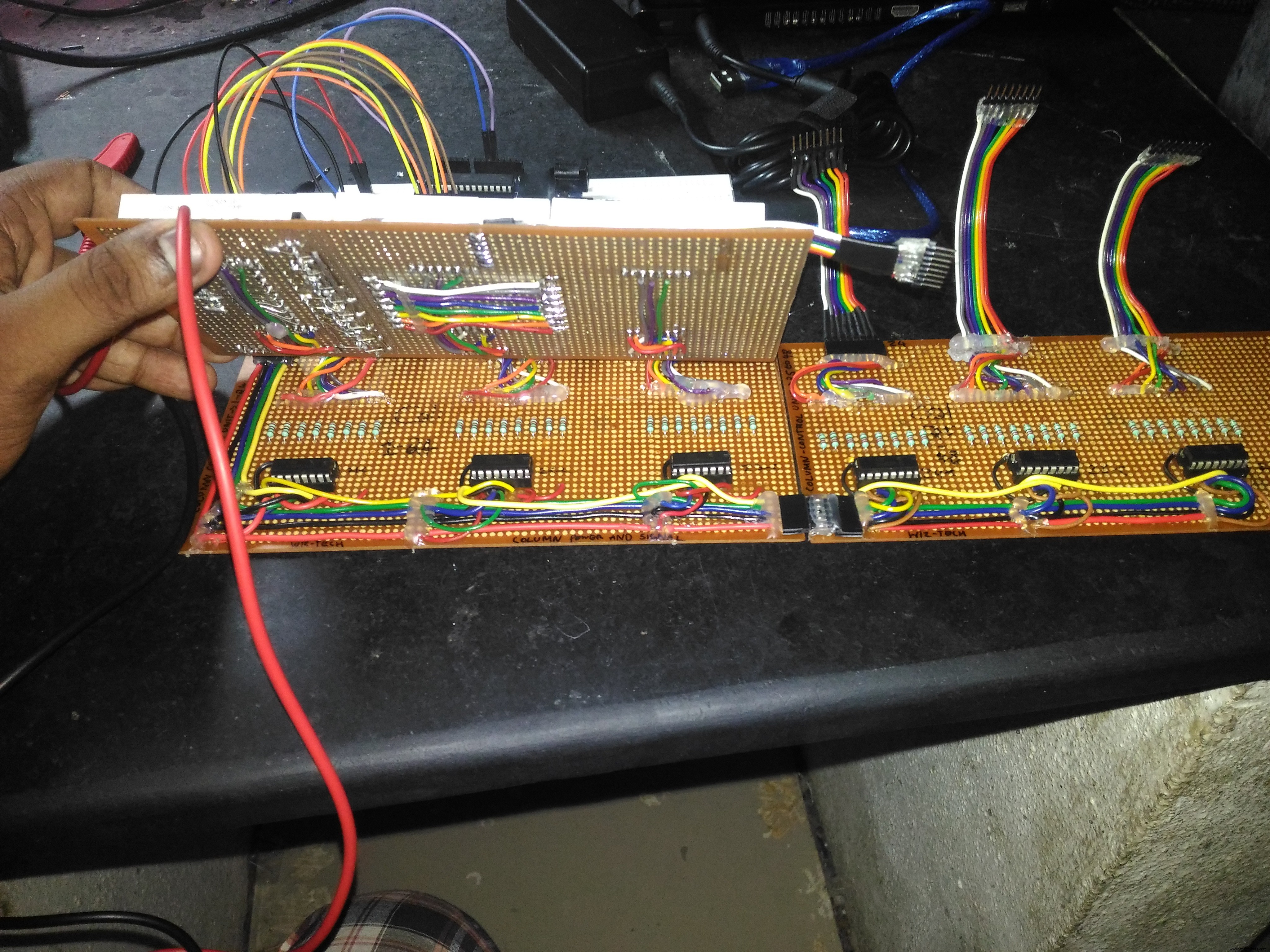
Soldering Stage
I took seperate dot boards to make the row and column controls and extended wires and headers to connect them together.
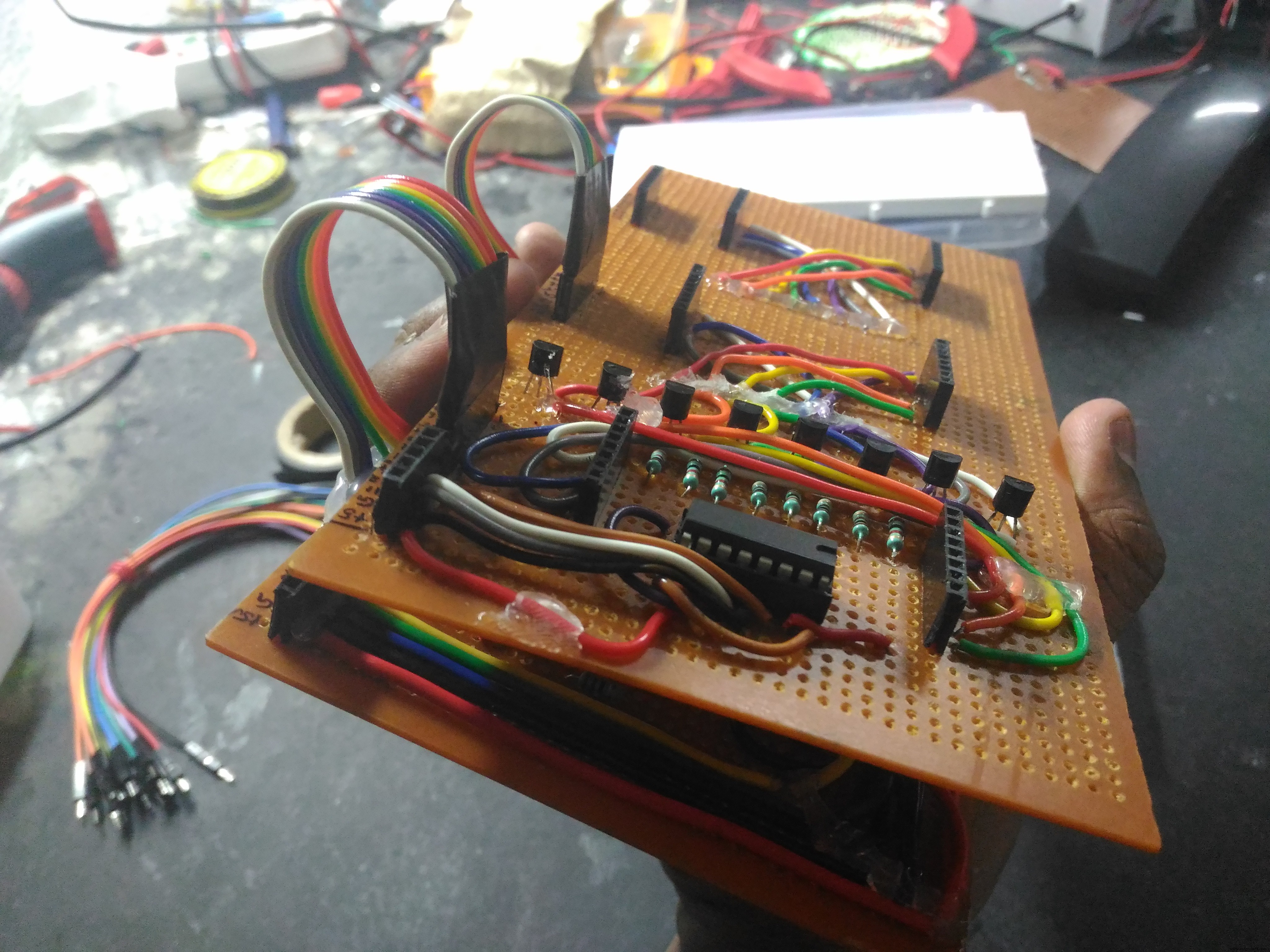
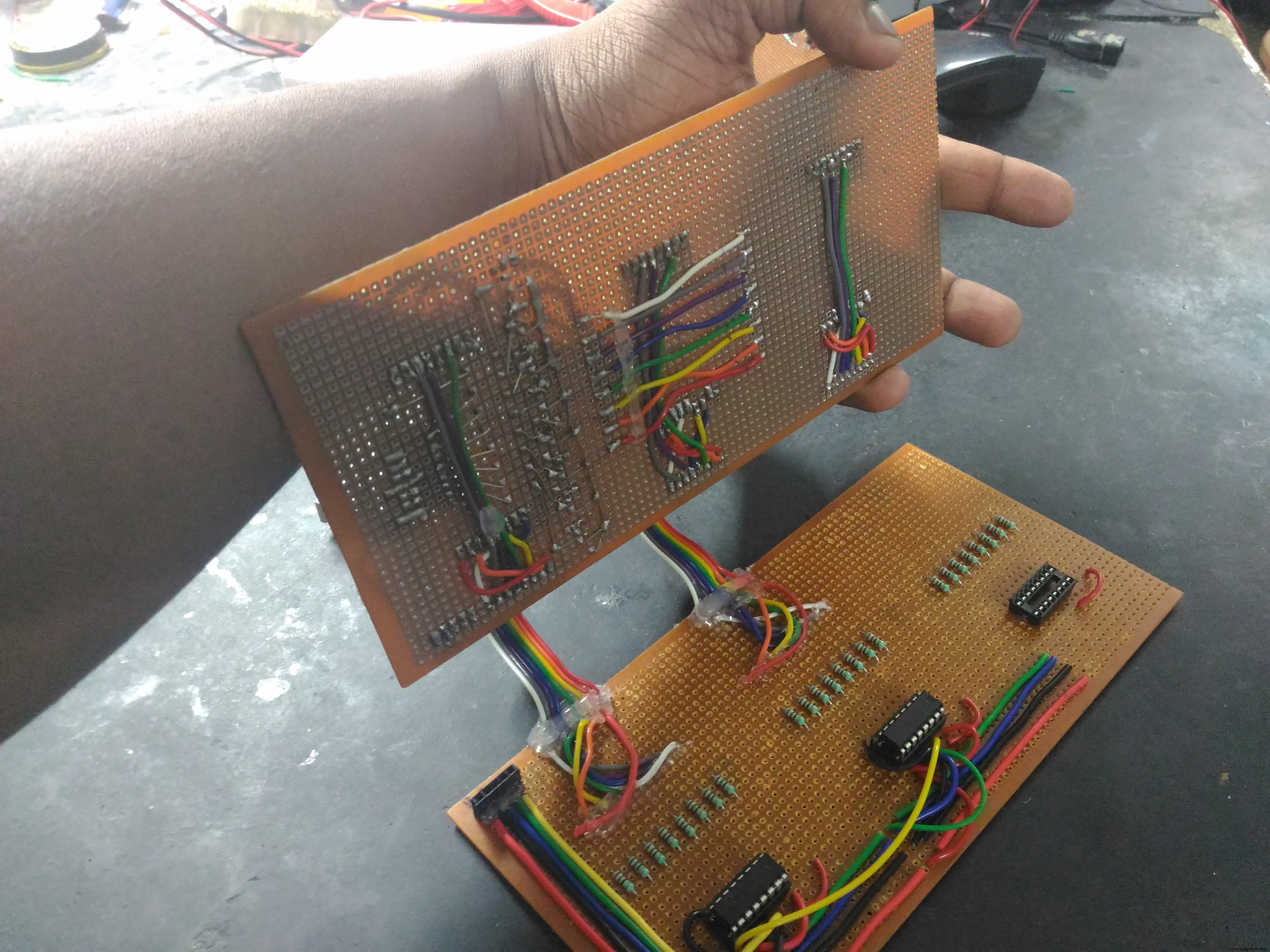
Once you've successfully made a 8x8 matrix you just need to daisy-chain more shift registers with common clock to drive the columns. it just need a single 74hc595 to drive all rows. So based on the number of columns, more shift registers can be added, there is no limit for the number of columns you can add.
Building the Second Half
As i didn't had access to 3D printing at that time, i approached a local carpenter to make a case.
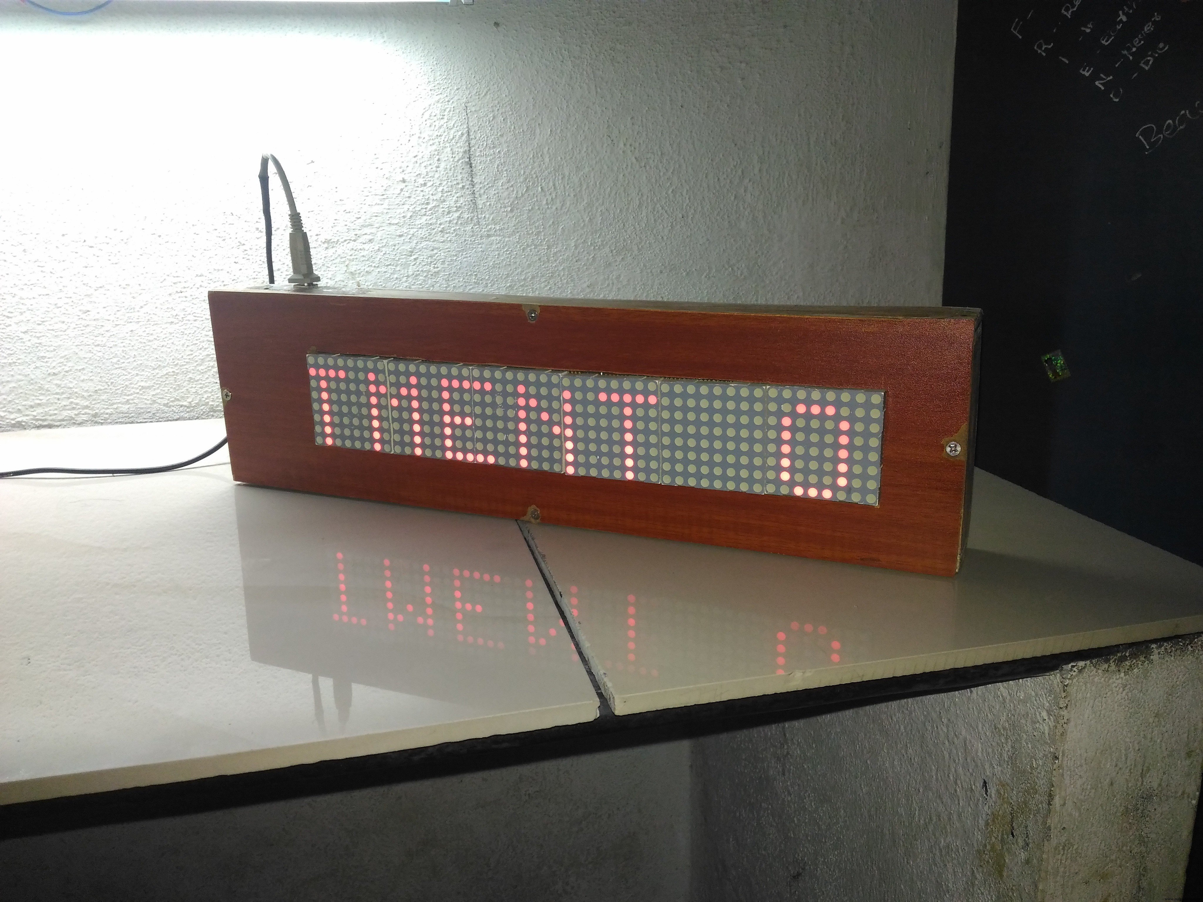
The case he made was much larger than i expected, it's better to design a smaller case using Fusion 360 or any other design software and 3D print the case. Holes were made in the case to connect the power and usb cables.
The Code
The Code can be found in the attachments with this project.
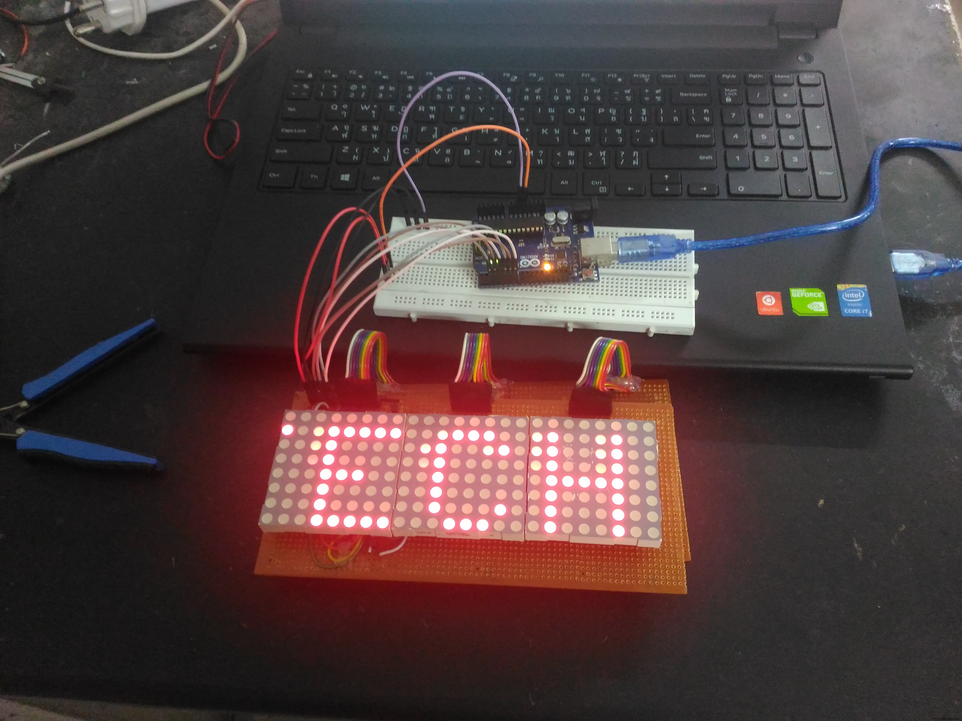
Here we will be scanning across the rows and feed the column lines with appropriate logic levels. The code will determine the speed of the scrolling message as well as the message that we are going to display. The direction of the scroll is right to left by default in the code, but with a little modification, it can be implemented in other directions too.
The Result
Thank you! :)
Code
- Arduino Code for 48x8 LED Matrix
Arduino Code for 48x8 LED MatrixC/C++
Aduino code for 48x8 LED Matrix. The connections and the code are explained as comments in the code itself./*////////////////////////////////////////////////////////////////////////////////
* Arduino code to display scrolling characters on 6 or more 8x8 LED matrix. *
* The no: of matrices can be increased with a small change in code. *
* Comments are given in each statement for editing. *
* Coded by Prasanth K S *
* Contact : kksjunior@hotmail.com *
/*////////////////////////////////////////////////////////////////////////////////
char msg[] ="WELCOME WIZ";//Change the text here.
int scrollspeed=5;//Set the scroll speed ( lower=faster)
int x;
int y;
//Columns
int clockPin1 = 2; //Arduino pin connected to Clock Pin 11 of 74HC595
int latchPin1 = 3; //Arduino pin connected to Latch Pin 12 of 74HC595
int dataPin1 = 4; //Arduino pin connected to Data Pin 14 of 74HC595
//Rows
int clockPin2 = 5; //Arduino pin connected to Clock Pin 11 of 74HC595
int latchPin2 = 6; //Arduino pin connected to Latch Pin 12 of 74HC595
int dataPin2 = 7; //Arduino pin connected to Data Pin 14 of 74HC595
//BITMAP
//Bits in this array represents one LED of the matrix
// 8 is # of rows, 6 is # of LED matrices
byte bitmap[8][7];
int numZones = sizeof(bitmap) / 8; // One Zone refers to one 8 x 8 Matrix ( Group of 8 columns)
int maxZoneIndex = numZones-1;
int numCols = numZones * 8;
//FONT DEFENITION
byte alphabets[][8] = {
{0,0,0,0,0},//@ as SPACE
//{8,28,54,99,65},//<<
{31, 36, 68, 36, 31},//A
{127, 73, 73, 73, 54},//B
{62, 65, 65, 65, 34},//C
{127, 65, 65, 34, 28},//D
{127, 73, 73, 65, 65},//E
{127, 72, 72, 72, 64},//F
{62, 65, 65, 69, 38},//G
{127, 8, 8, 8, 127},//H
{0, 65, 127, 65, 0},//I
{2, 1, 1, 1, 126},//J
{127, 8, 20, 34, 65},//K
{127, 1, 1, 1, 1},//L
{127, 32, 16, 32, 127},//M
{127, 32, 16, 8, 127},//N
{62, 65, 65, 65, 62},//O
{127, 72, 72, 72, 48},//P
{62, 65, 69, 66, 61},//Q
{127, 72, 76, 74, 49},//R
{50, 73, 73, 73, 38},//S
{64, 64, 127, 64, 64},//T
{126, 1, 1, 1, 126},//U
{124, 2, 1, 2, 124},//V
{126, 1, 6, 1, 126},//W
{99, 20, 8, 20, 99},//X
{96, 16, 15, 16, 96},//Y
{67, 69, 73, 81, 97},//Z
};
void setup() {
pinMode(latchPin1, OUTPUT);
pinMode(clockPin1, OUTPUT);
pinMode(dataPin1, OUTPUT);
pinMode(latchPin2, OUTPUT);
pinMode(clockPin2, OUTPUT);
pinMode(dataPin2, OUTPUT);
//Clear bitmap
for (int row = 0; row < 8; row++) {
for (int zone = 0; zone <= maxZoneIndex; zone++) {
bitmap[row][zone] = 0;
}
}
}
//FUNCTIONS
// Displays bitmap array in the matrix
void RefreshDisplay()
{
for (int row = 0; row < 8; row++) {
int rowbit = 1 << row;
digitalWrite(latchPin2, LOW);//Hold latchPin LOW for transmitting data
shiftOut(dataPin2, clockPin2, MSBFIRST, rowbit); //Transmit data
//Start sending column bytes
digitalWrite(latchPin1, LOW);//Hold latchPin LOW for transmitting data
//Shift out to each matrix
for (int zone = maxZoneIndex; zone >= 0; zone--)
{
shiftOut(dataPin1, clockPin1, MSBFIRST, bitmap[row][zone]);
}
//flip both latches at once to eliminate flicker
digitalWrite(latchPin1, HIGH);//Return the latch pin 1 high to signal chip
digitalWrite(latchPin2, HIGH);//Return the latch pin 2 high to signal chip
//Wait
delayMicroseconds(300);
}
}
// Converts row and colum to bitmap bit and turn it off/on
void Plot(int col, int row, bool isOn)
{
int zone = col / 8;
int colBitIndex = x % 8;
byte colBit = 1 << colBitIndex;
if (isOn)
bitmap[row][zone] = bitmap[y][zone] | colBit;
else
bitmap[row][zone] = bitmap[y][zone] & (~colBit);
}
// Plot each character of the message one column at a time, updated the display, shift bitmap left.
void XProcess()
{
for (int charIndex=0; charIndex < (sizeof(msg)-1); charIndex++)
{
int alphabetIndex = msg[charIndex] - '@';
if (alphabetIndex < 0) alphabetIndex=0;
//Draw one character of the message
// Each character is 5 columns wide, loop two more times to create 2 pixel space betwen characters
for (int col = 0; col < 7; col++)
{
for (int row = 0; row < 8; row++)
{
// Set the pixel to what the alphabet say for columns 0 thru 4, but always leave columns 5 and 6 blank.
bool isOn = 0;
if (col<5) isOn = bitRead( alphabets[alphabetIndex][col], 7-row ) == 1;
Plot( numCols-1, row, isOn); //Draw on the rightmost column, the shift loop below will scroll it leftward.
}
for (int refreshCount=0; refreshCount < scrollspeed; refreshCount++)
RefreshDisplay();
//Shift the bitmap one column to left
for (int row=0; row<8; row++)
{
for (int zone=0; zone < numZones; zone++)
{
//This right shift would show as a left scroll on display because leftmost column is represented by least significant bit of the byte.
bitmap[row][zone] = bitmap[row][zone] >> 1;
// Shift over lowest bit from the next zone as highest bit of this zone.
if (zone < maxZoneIndex) bitWrite(bitmap[row][zone], 7, bitRead(bitmap[row][zone+1],0));
}
}
}
}
}
void loop() {
XProcess();
}
Schematics
For Reference purpose only. For pin connections, refer to the comments in the code.
Manufacturing process
- Build a Smart Arduino Quadruped Robot: Step‑by‑Step Guide
- Seamless LED Brightness Control Using Bolt IoT and Arduino UNO
- Arduino Flip Clock with 8×8 LED Matrix – DIY Real‑Time Clock Project
- Mastering an 8×8 LED Matrix with Arduino Uno: A Step‑by‑Step Guide
- Bluetooth‑Enabled 8x8 LED Matrix with Scrolling Text – Arduino Project
- Build an Arduino Snake Game on an 8x8 LED Matrix
- Build an Infinity Gauntlet: DIY Arduino LED Kit
- Build a Snake Game on a 16x16 LED Matrix with Arduino UNO
- Mini LED Matrix Clock – Arduino Nano Powered Timepiece
- Master WS2812B LED Control with Arduino – Step‑by‑Step Guide