


Efficiently Control 10 Buttons with a Single Interrupt on Arduino UNO
Components and supplies
 |
| × | 1 | |||
 |
| × | 1 | |||
 |
| × | 21 | |||
 |
| × | 10 |
Apps and online services
 |
|
About this project
IntroductionInterrupts are handy. They, in addition to sometimes making code simpler, can be used for precise timing or for waking the Arduino up from sleep mode.
Let's say you've got a user interface, a remote controller, for example, that runs on batteries. You might want to put the Arduino (or stand-alone ATmega) to power-down mode to save power. When an Arduino enters power-down mode it can only be woken up by an external interrupt. The ATmega328P chip used in an Arduino Uno has only two external pin interrupts. (INT0 and INT1 on pins 2 and 3) Since a user interface is likely to have more than two buttons, that's a problem.
The standard way to solve
this would be to connect all buttons normally, but to also connect them to an interrupt pin with a diode. This does, however, complicate the circuit significantly.
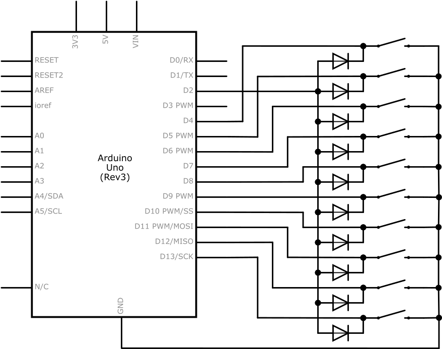
In addition to standard external interrupts, the ATmega328P also has pin change interrupts. There are libraries to deal with them and they are a good solution to this problem.
However, during a programming competition, I figured out how to do this using standard external interrupts with no extra electrical components.
The circuit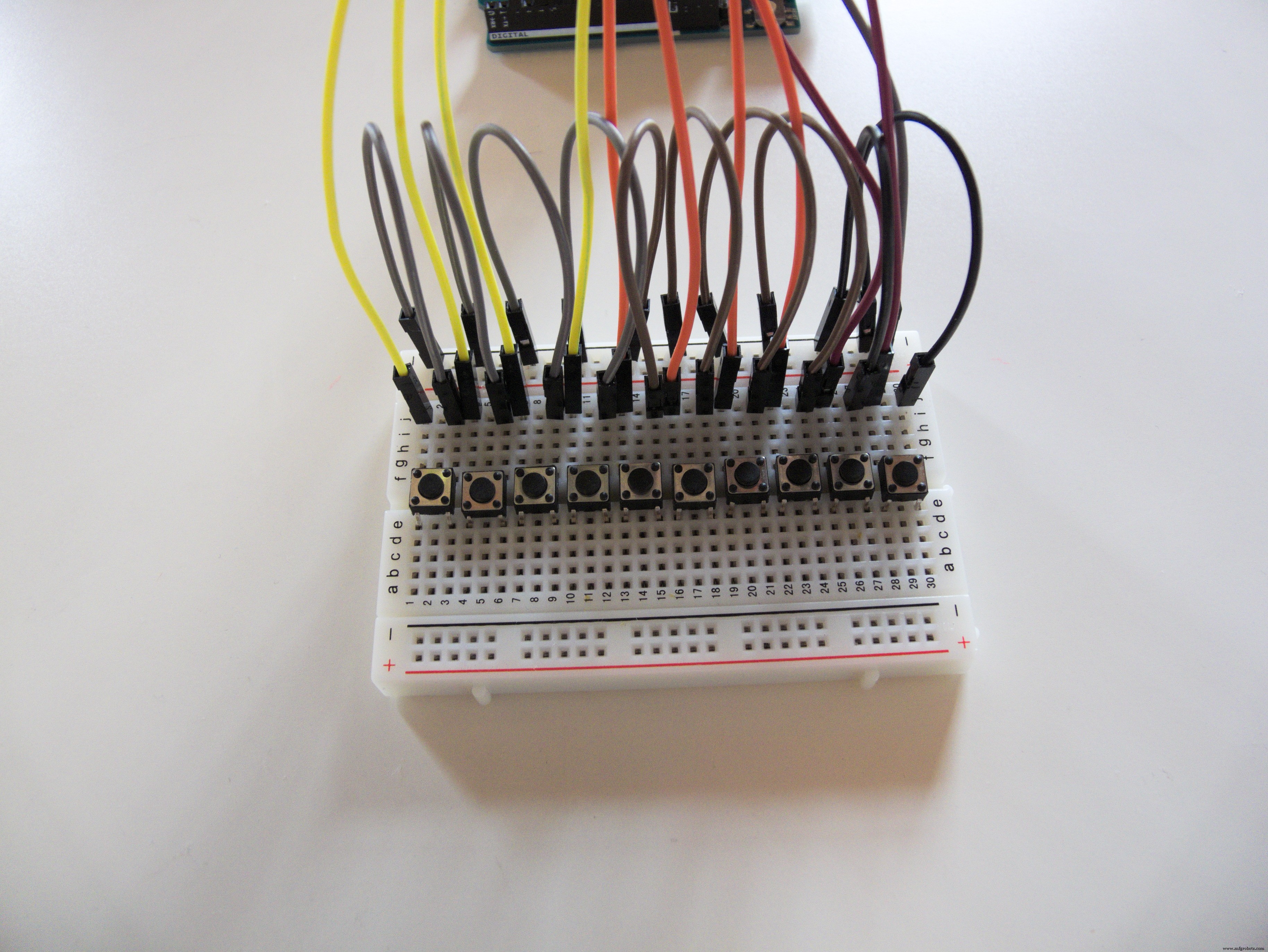
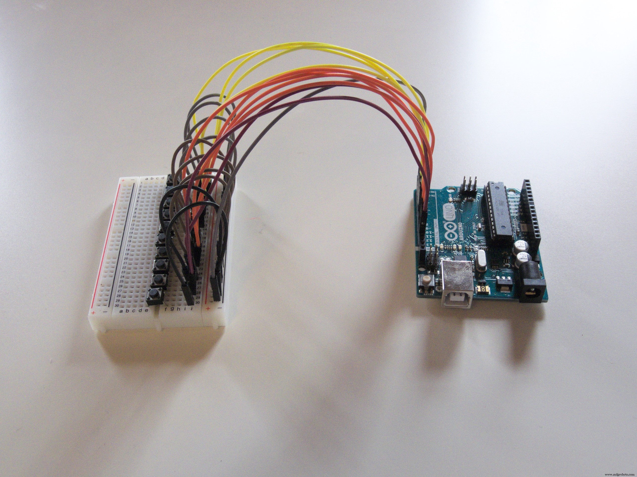
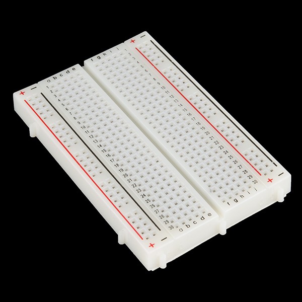
We have a few buttons. I used ten, which fit nicely on my breadboard. (I also don't have more.) You can have one button per pin, which means up to 20 on a Uno and up to 70 on a Mega! (If you actually need 70 buttons, I recommend using multiplexing, you don't need an entire Mega for that.)
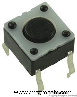
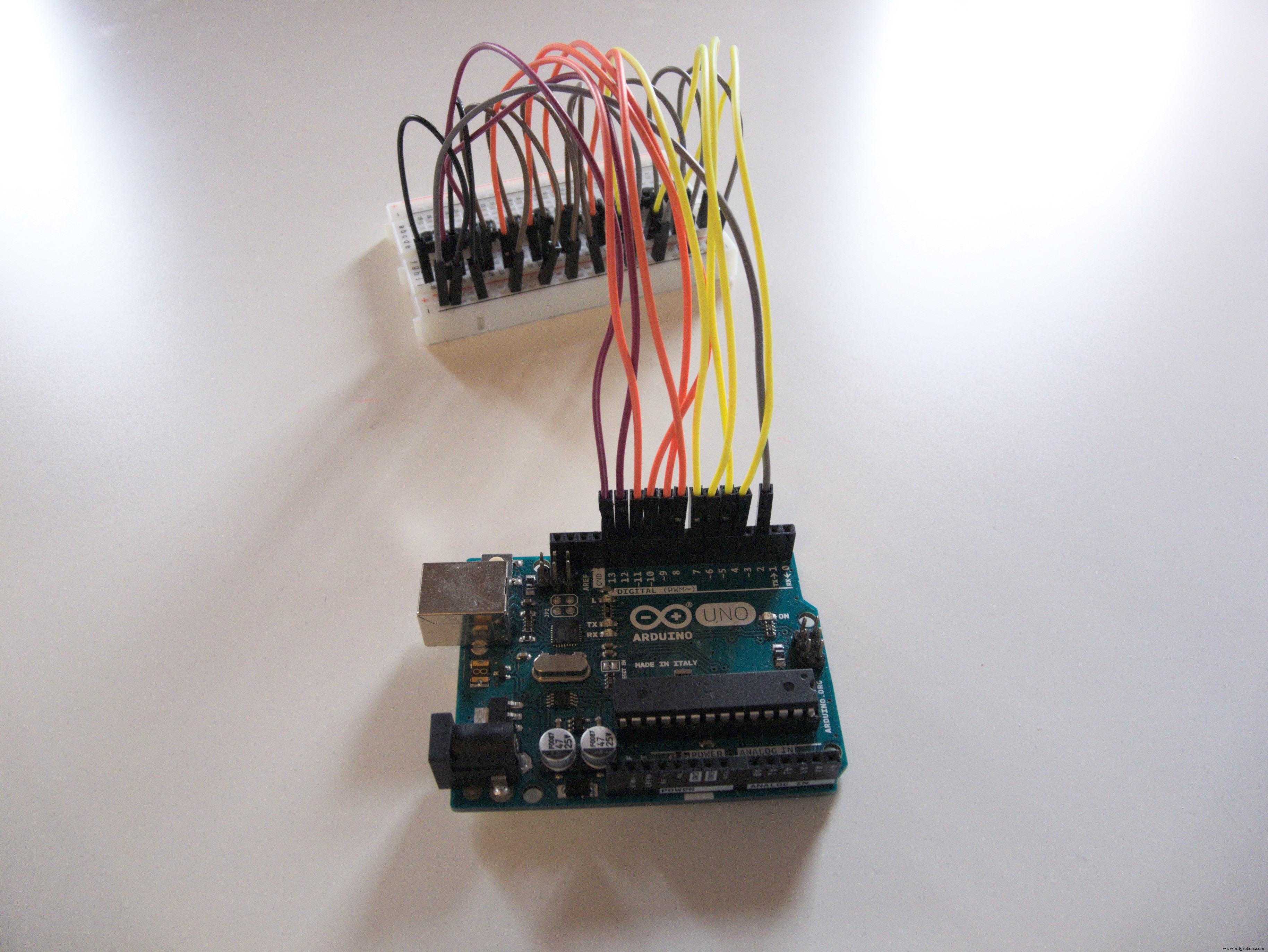
Each button has one side connected to an arbitrary pin. (4-13 in my case) The other sides of all buttons are connected together to a single interrupt-capable pin. (2 in my case)
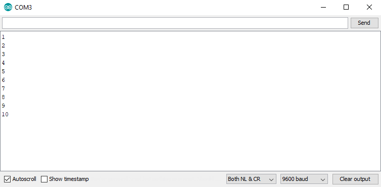
The code is attached below. To get this example to work, upload it to your board. Open your serial monitor. When you press a button, its number will appear. As you can see, the loop function is not used at all.
There is, obviously, an interrupt. In my case, it's attached to pin 2. It's configured as FALLING.
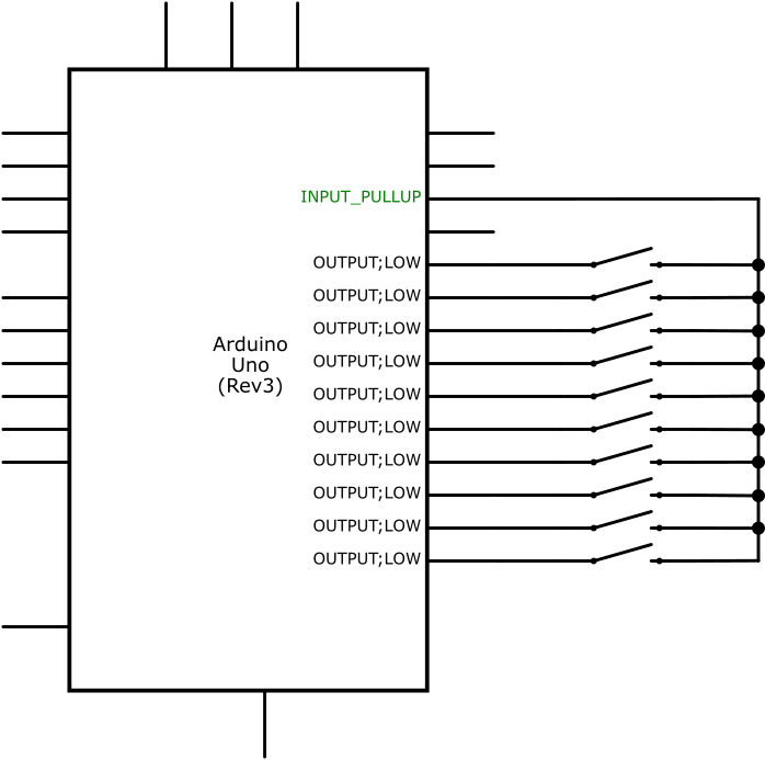
To avoid using diodes, the Arduino rewires the circuit on the fly. There are two possible configurations: Common mode and Distinct mode.
Common modeMost of the time, the circuit will be in common mode. The interrupt pin will be configured as INPUT_PULLUP and the rest will be OUTPUT and LOW.
void configureCommon() {
 pinMode(commonPin, INPUT_PULLUP);
 for (int i = 0; i < sizeof(buttonPins) / sizeof(int); i++) {
   pinMode(buttonPins[i], OUTPUT);
   digitalWrite(buttonPins[i], LOW);
 }
}
In common mode, pressing any button will pull our interrupt pin down and fire our interrupt. Once that happens, our interrupt service routine will reconfigure the pins for distinct mode.
Distinct modeOnce our interrupt triggers, we quickly switch to distinct mode.
Distinct mode is the opposite of common mode. The interrupt pin will be OUTPUT and LOW and the rest will be INPUT_PULLUP.
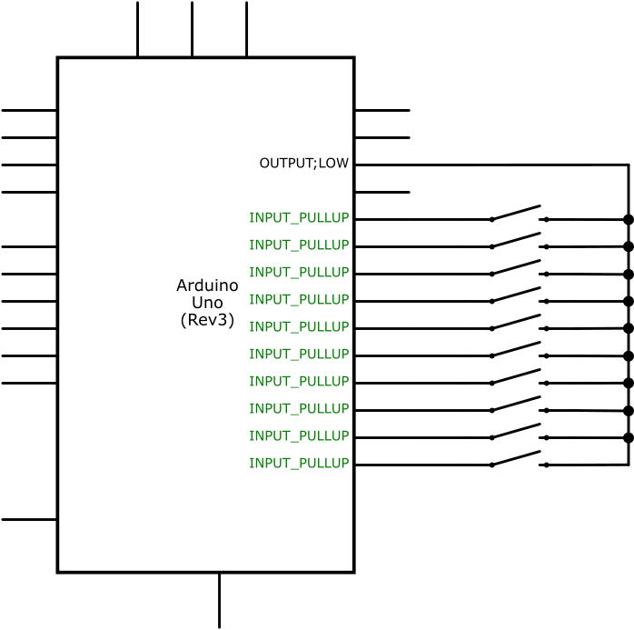
void configureDistinct() {
 pinMode(commonPin, OUTPUT);
 digitalWrite(commonPin, LOW);
 for (int i = 0; i < sizeof(buttonPins) / sizeof(int); i++) {
   pinMode(buttonPins[i], INPUT_PULLUP);
 }
}
In distinct mode, only pins corresponding to buttons actually pressed will be pulled down. We can easily go over all pins to find out which one triggered the interrupt.
After that's done, the Arduino can switch back to common mode and wait for another interrupt. Or, depending on your application, it can stay in distinct mode and process user input as it would normally, switching back to common mode before the Arduino goes to sleep.
A more complex exampleLet's try something a bit more complex. We'll attach a servo and map each button to a different angle. (1=0°, 2=20°... 10=120°) We'll also power our Arduino with a few batteries.
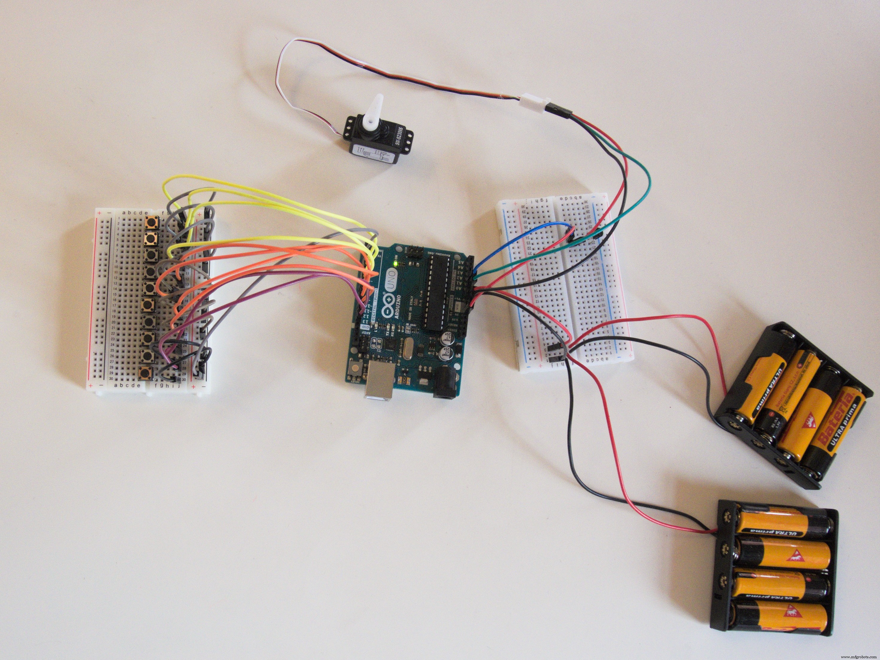
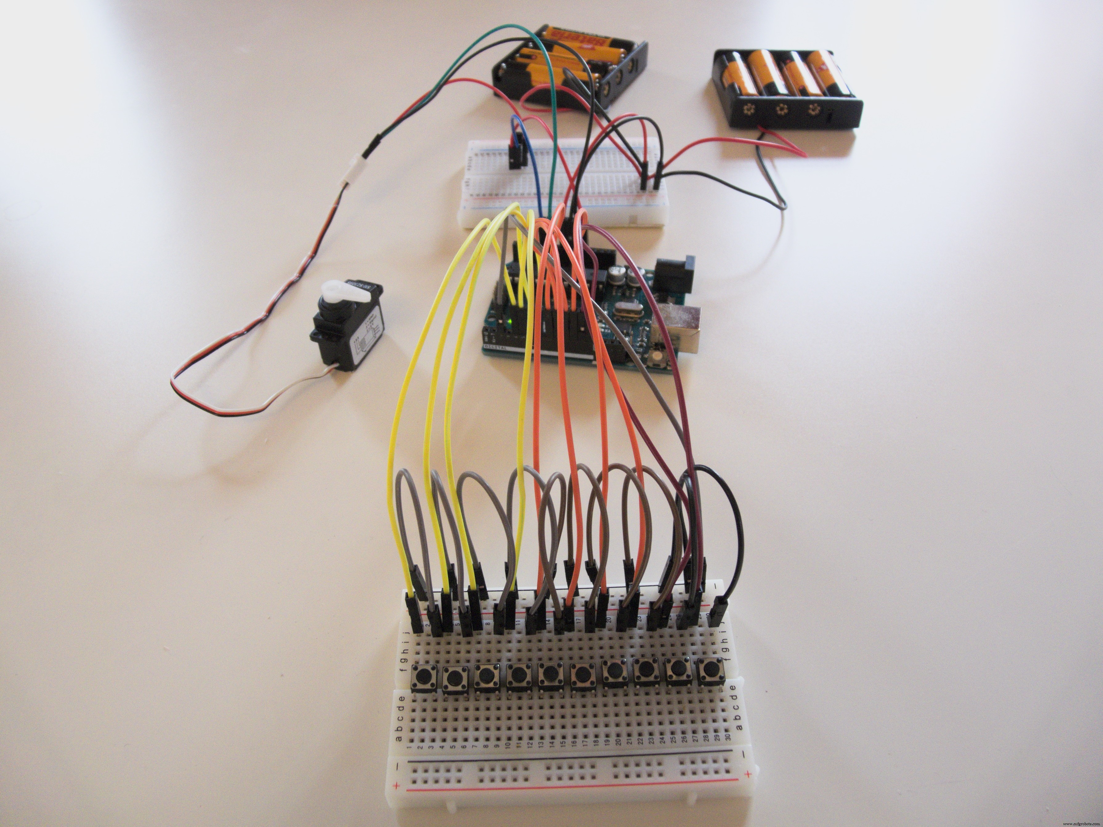
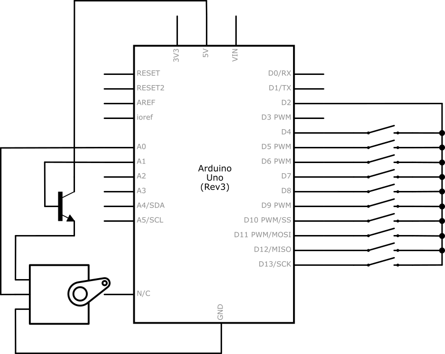
In this example, we put the Arduino to power-down mode after five seconds of inactivity to conserve power. You can find some tutorials on sleep mode online. In addition to that, we power the servo through a transistor to shut it down when it's not in use.
The code for this example is also attached below.
Code
- Serial logger
- Servo with sleep mode
Serial loggerArduino
const int commonPin = 2;
const int buttonPins[] = {4,5,6,7,8,9,10,11,12,13};

unsigned long lastFire = 0;

void setup() {
  configureCommon(); // Setup pins for interrupt

  attachInterrupt(digitalPinToInterrupt(commonPin), pressInterrupt, FALLING);

  Serial.begin(9600);
}

void loop() {
  // Empty!
}

void pressInterrupt() { // ISR
  if (millis() - lastFire < 200) { // Debounce
    return;
  }
  lastFire = millis();

  configureDistinct(); // Setup pins for testing individual buttons

  for (int i = 0; i < sizeof(buttonPins) / sizeof(int); i++) { // Test each button for press
    if (!digitalRead(buttonPins[i])) {
      press(i);
    }
  }

  configureCommon(); // Return to original state
}

void configureCommon() {
  pinMode(commonPin, INPUT_PULLUP);

  for (int i = 0; i < sizeof(buttonPins) / sizeof(int); i++) {
    pinMode(buttonPins[i], OUTPUT);
    digitalWrite(buttonPins[i], LOW);
  }
}

void configureDistinct() {
  pinMode(commonPin, OUTPUT);
  digitalWrite(commonPin, LOW);

  for (int i = 0; i < sizeof(buttonPins) / sizeof(int); i++) {
    pinMode(buttonPins[i], INPUT_PULLUP);
  }
}

void press(int button) { // Our handler
  Serial.println(button + 1);
}
Servo with sleep modeArduino
#include <Servo.h>
#include <avr/sleep.h>
#include <avr/power.h>

const int commonPin = 2;
const int buttonPins[] = {4,5,6,7,8,9,10,11,12,13};

const int servoEnablePin = A1;
const int servoPin = A0;
Servo servo;

unsigned long lastFire = 0;
int status = 0;

void setup() {
  pinMode(commonPin, INPUT_PULLUP);

  configureCommon();

  attachInterrupt(digitalPinToInterrupt(commonPin), pressInterrupt, FALLING);

  servo.attach(servoPin);
  pinMode(servoEnablePin, OUTPUT);
}

void loop() {
  if (millis()-lastFire > 5000) {
    digitalWrite(servoEnablePin, LOW);

    set_sleep_mode(SLEEP_MODE_PWR_DOWN);
    sleep_enable();
    sleep_mode();
  }

  delay(10);
}

void pressInterrupt() {
  sleep_disable();
  power_all_enable();

  if (millis()-lastFire < 200) {
    return;
  }
  lastFire = millis();

  configureDistinct();

  for (int i=0;i<sizeof(buttonPins)/sizeof(int);i++) {
    if (!digitalRead(buttonPins[i])) {
      press(i);
    }
  }

  configureCommon();
}

void configureCommon() {
  pinMode(commonPin, INPUT_PULLUP);

  for (int i=0;i<sizeof(buttonPins)/sizeof(int);i++) {
    pinMode(buttonPins[i], OUTPUT);
    digitalWrite(buttonPins[i], LOW);
  }
}

void configureDistinct() {
  pinMode(commonPin, OUTPUT);
  digitalWrite(commonPin, LOW);

  for (int i=0;i<sizeof(buttonPins)/sizeof(int);i++) {
    pinMode(buttonPins[i], INPUT_PULLUP);
  }
}

void press(int button) {
  digitalWrite(servoEnablePin, HIGH);
  servo.write(map(button,0,9,0,180));
}
Schematics

 multiinterrupt_hoF76Oc4T5.fzzservo_with_sleep_u9ZqxF0jhY.fzz
Manufacturing process
- Create a Stunning Monitor Ambilight System with Arduino
- Build a Smart Voltmeter with Arduino & Smartphone – Easy DIY Project
- Real‑Time IoT Heart Rate Monitor with Arduino & MAX30100
- Arduino Uno WiFi Web Server: Toggle an LED via Browser
- Build an Arduino-Powered Automated Google Chrome Dino Game
- Build a Compact FM Radio with Arduino Nano and RDA8057M
- Wireless Arduino Programming Shield with HC-05 Bluetooth – No USB Needed
- Capacitive Touch LED Switch with Arduino UNO – Easy DIY Project
- Build a Real-Time Face-Tracking System with Arduino & OpenCV
- Build a Precise Clock with Arduino Nano and 16x2 LCD