


DIY 1 MHz Square Wave Generator with Arduino Nano – Easy PWM Circuit
Components and supplies
 |
| × | 1 | |||
 |
| × | 1 | |||
 |
| × | 3 | |||
 |
| × | 1 |
Apps and online services
 |
|
About this project
This is a simple square-wave generator that basically uses the TimerOne library allow you to generate a PWM signal at pin 9 in the range from about 5Hz to 1 Mhz, and you can adjust the duty cycle from 0 to 100%.
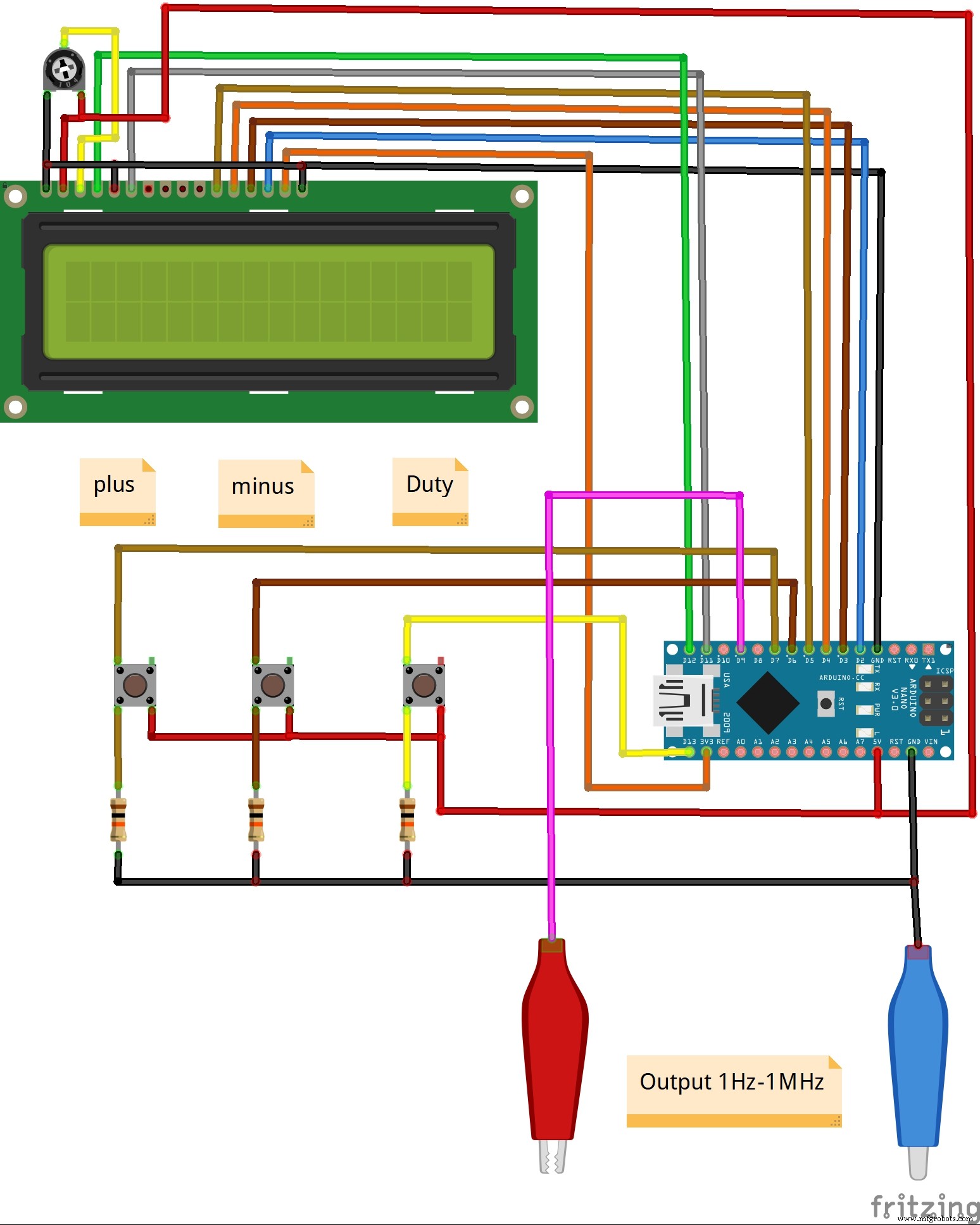
Device is very simple to build and consist only a few components:
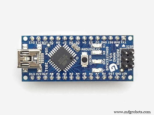
- Arduino Nano microcontroller
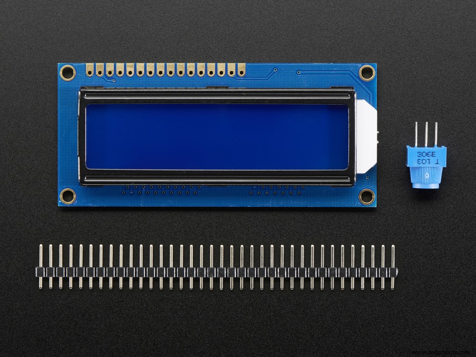
- LCD display
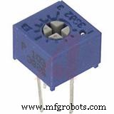
- Three pull up resistors
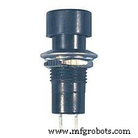
- and three push buttons
The pulse generator has the ability to adjust the pulse repetition period using the buttons connected to digital inputs 6 and 7 of the Arduino. 13 input pin allows you to adjust the duty cycle. The duration and duty cycle readings are displayed on the first row of the LCD 16 × 2 indicator, and the frequency readings are displayed in the second row. The minimum step for adjusting the pulse repetition period is 1 μs, so the frequency will change discretely, for example, 1 μs is 1 MHz, 2 μs is 500 kHz, 3 μs is 333.333 Hz, and so on, and as the frequency decreases, the smoothness of its adjustment increases. This is quite impractical at higher frequencies but that is the price of simplicity. In one of my previous videos I have described the construction of a similar device but with the help of a specialized DDS chip that does not have these shortcomings and has a much larger range, but is more complex to build
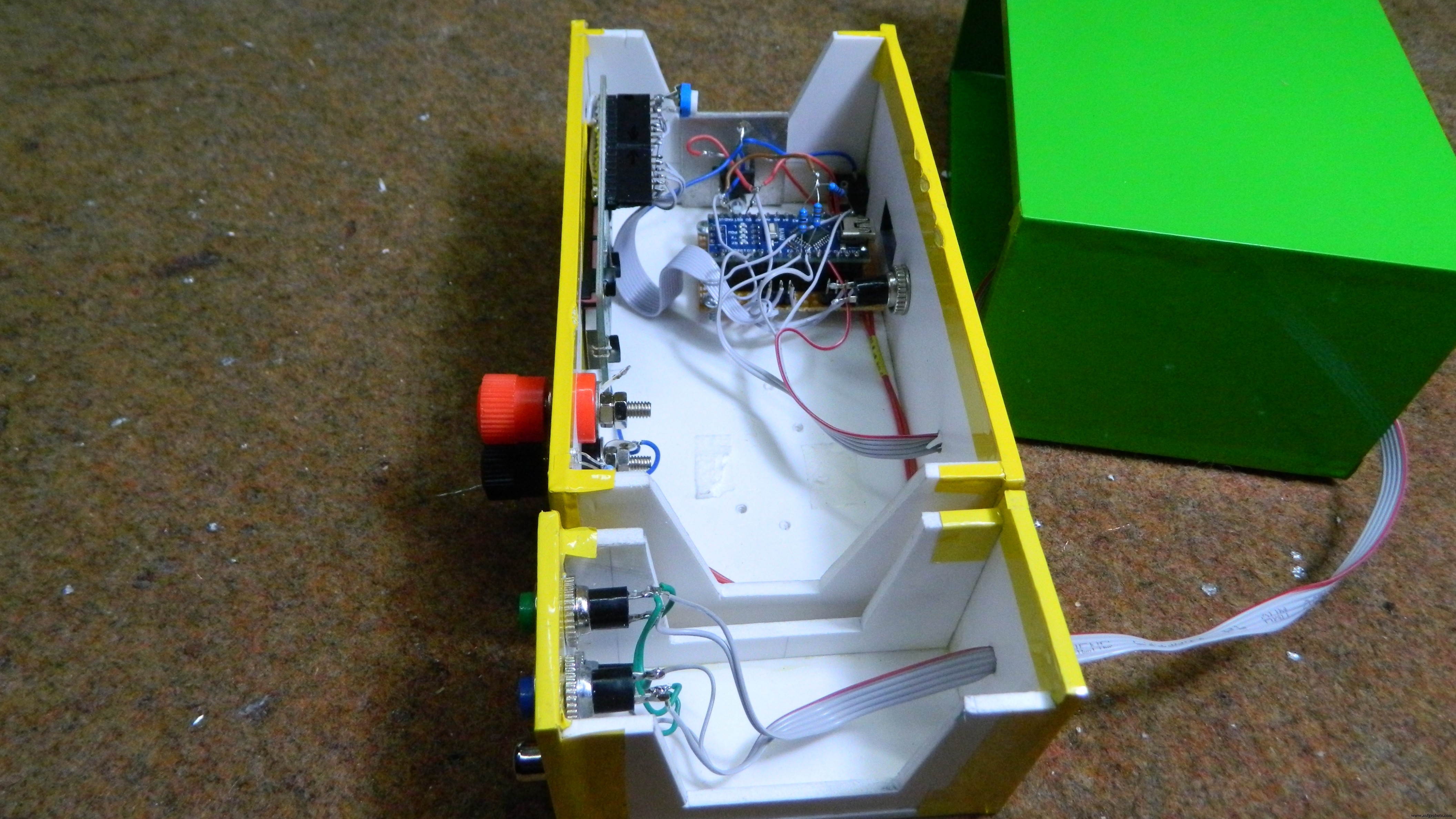
To visualize the output signal I use small single- channel oscilloscope. Finally, the device is mounted in a suitable box, and it is another useful tool in the electronics laboratory.
Code
- Arduino code
Arduino codeC/C++
#include <TimerOne.h>
#include <LiquidCrystal.h>
LiquidCrystal lcd(12, 11, 5, 4, 3, 2);// RS,E,D4,D5,D6,D7
unsigned long t=1000,f,k=512;// default 1000 μs (1000 Hz), meander, pulse


byte k1,kn,kn1,kn2;
int drive,drive0;

void setup()
{
  lcd.begin(16, 2);// LCD 16X2
  pinMode(9, OUTPUT);
  pinMode(6,INPUT);// button at input 6
  pinMode(7,INPUT);// button at input 7
  pinMode(13,INPUT);// button at input 13
}
void loop()
{
  Timer1.initialize(t); // period
  Timer1.pwm(9, k); // k - fill factor 0-1023.
  kn=digitalRead(6);// button input 6 (- pulse period)
  kn1=digitalRead(7);// button input 7 (+ pulse period)
  kn2=digitalRead(13);// button input 13 (+ circle fill factor)

  if(kn==HIGH){ // decreasing the period
    drive++;
    if(drive<30){
      t=t-1;
    }
    // if the button is held for a long time, the correction of the pulse


    else if(drive>30 && drive<60 ){
      t=t-10;
    }
    else if(drive>=60 && drive<100){
      t=t-100;
    }
    else if(drive>=100){
      t=t-1000;
    }
  }
  else{
    drive=0;
  }

  if(kn1==HIGH){// adding a period
    drive0++;
    if(drive0<30){
      t=t+1;
      // if the button is held for a long time, the correction of the


    }
    else if(drive0>30 && drive0<60 ){
      t=t+10;
    }
    else if(drive0>=60 && drive0<100){
      t=t+100;
    }
    else if(drive0>=100){
      t=t+1000;
    }
  }
  else{
    drive0=0;
  }
  if(t==0 || t>300000){ // limiting the pulse duration to the minimum, if


    t=1;
  }
  if(t>200000 && t<300000){ // limiting the pulse duration to the


    t=200000;
  }
  f=1000000/t; // calculate the frequency
  k1=k*100/1024; // calculate% fill factor

  if(kn2==HIGH){// button for adjusting the fill factor (in a circle from


    k=k+16;// step 16 out of 1024 (you can do 8 for smoother adjustment)
  }
  if(k==1024){
    k=0;
  }
// displaying information on the indicator
  lcd.setCursor(0,0);
  lcd.print("T=");
  lcd.print(t);
  lcd.print(" us");
  lcd.setCursor(12,0);
  lcd.print(k1);
  lcd.print(" %");
  lcd.setCursor(0,1);
  lcd.print("F=");
  lcd.print(f);
  lcd.print(" Hz");
  delay(300);
  lcd.setCursor(0,0);
  lcd.print("                ");
  lcd.setCursor(0,1);
  lcd.print("                ");
}
Schematics
Manufacturing process
- Understanding Square Wave Signals: Fundamentals and Applications
- DIY Arduino Word Clock – Build a Sleek Real-Time Display
- Build a 20 kHz Arduino Oscilloscope on a Nokia 5110 LCD – Easy DIY Guide
- JX Wave Generator – Arduino-Compatible DDS Oscillator with OLED Display
- Build a Precise DIY Measuring Wheel with Arduino Nano & Rotary Encoder
- Effortless Arduino Stopwatch: Build a Button-Activated Chronometer
- Build a Sensitive Metal Detector with Arduino Nano – DIY Guide
- Build a Complete Arduino‑Powered RC Airplane from Scratch
- Build an Arduino‑Powered RC Hovercraft: Full 3D‑Printed Design & Programming Guide
- Build a Multifunctional Arduino RC Transmitter: Step‑by‑Step DIY Guide