


Build a 20 kHz Arduino Oscilloscope on a Nokia 5110 LCD – Easy DIY Guide
Components and supplies
 |
| × | 1 | |||
| × | 1 | ||||
 |
| × | 4 | |||
 |
| × | 1 | |||
 |
| × | 1 | |||
 |
| × | 4 |
Necessary tools and machines
 |
| |||
|
|
Apps and online services
 |
|
About this project
This time I will show you how to make a simple Arduino oscilloscope. The maximum signal frequency that the oscilloscope can display is 20 kHz, and the maximum input voltage is 5 V without a voltage divider.
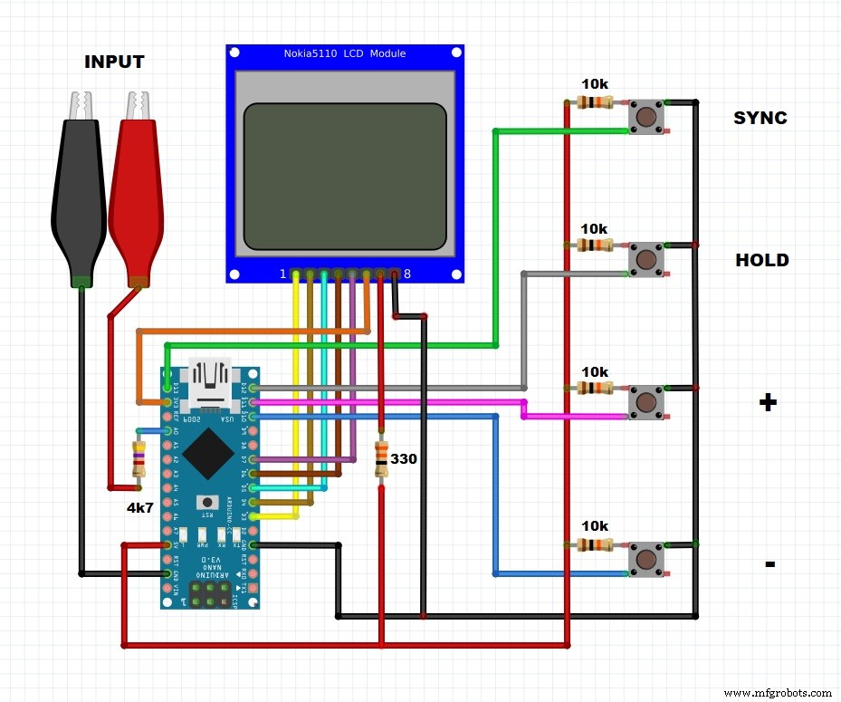
The oscilloscope is controlled by four buttons:
- "HOLD" button - which serves to freeze the current state of the screen
- Synchronization button that allows you to set the synchronization level.
- And Buttons "+" and "-" that control the sweep, sync level, and move the signal image in HOLD mode.
On the Nokia 5110 screen, vertically each cell is 1 V, horizontally one cell is equal to the scan resolution, which has the (following) values from: 0.1, 0.2, 0.5, 1.0, 2.0, 5.0, 10.0, 20.0 and 50.0 ms. The sweep value is changed with the "+" and "-" buttons, which is displayed in the upper left corner. The trigger level is displayed as a small bar on the left side of the screen, and the trigger voltage is displayed in the upper right corner of the screen. This project is published on arduino.ru page where you can read more details.
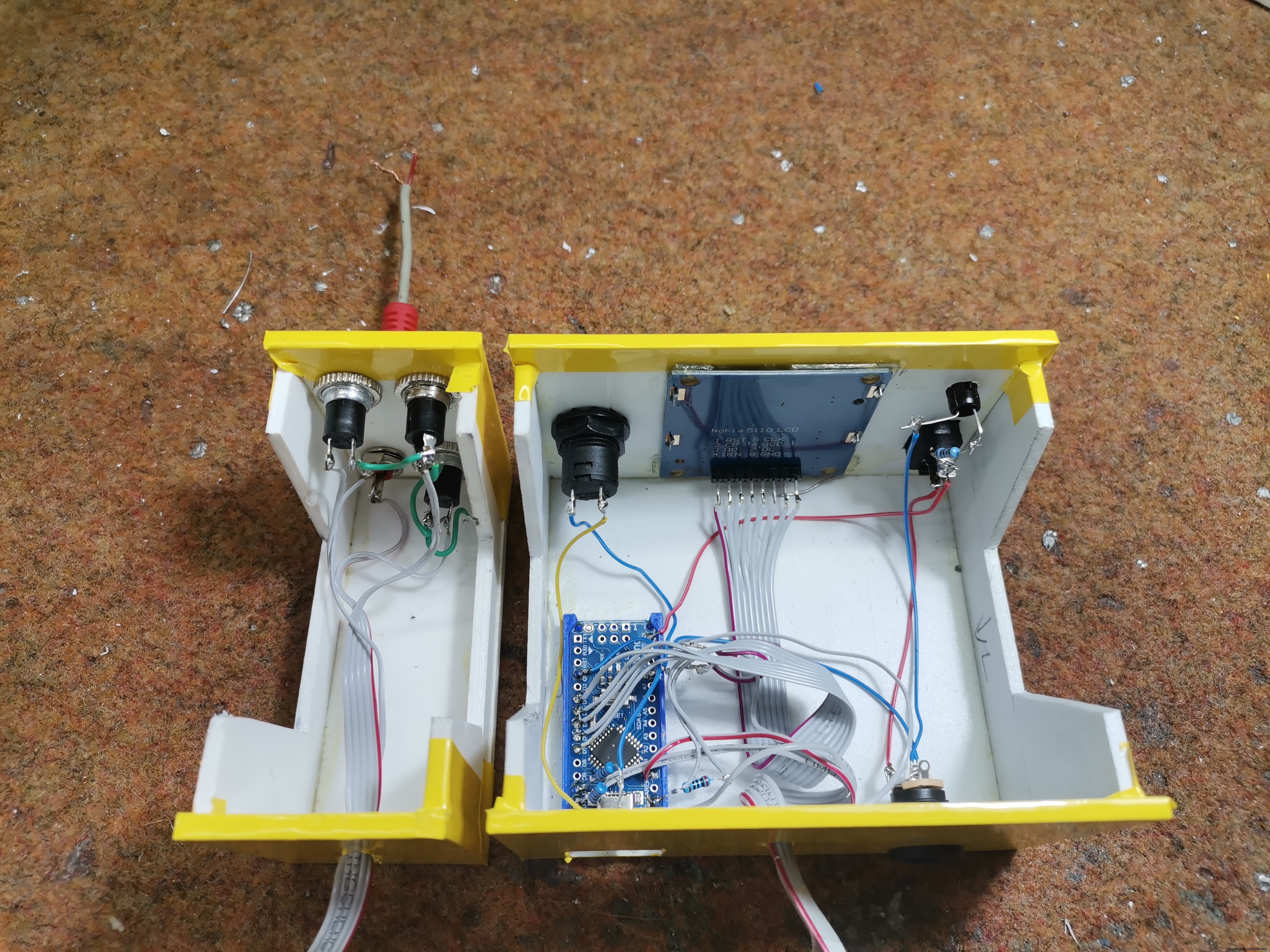
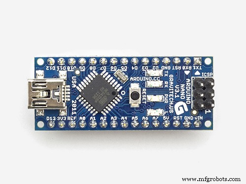
The device is extremely simple to build and consist of only a few components - Arduino Nano microcontroller
- Nokia N5110 LCD display
- four buttons
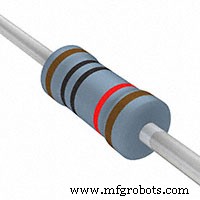
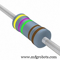
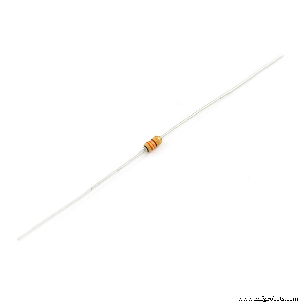
- four pull-down resistors
- Input jack
- And Power switch and Led
I tested the oscilloscope with sine and rectangular signal generator. Even though it is not a professional or very usable instrument, it can still be used for educational purposes or in your laboratory, for testing low-frequency signals, especially knowing that the device is very easy to make and extremely cheap.
Finally, the device is placed in a suitable box made of PVC and coated with self-adhesive wallpaper.
Code
- Arduino code
Arduino codeC/C++
#include <Adafruit_GFX.h>
#include <Adafruit_PCD8544.h>
#include <SPI.h>
Adafruit_PCD8544 display = Adafruit_PCD8544(7, 6, 5, 4, 3);//CLK,DIN,DC,CE,RST |||| VCC +3.3 V , BL ++ 200 OM ++ 3.3 V

int izm,x,y,u,i2,zz,hold,h0,h1,h2,raz=0,menu,sss=512,u_dig,data[168]{};
unsigned long time,times;
float per;
byte i;

void setup() {Serial.begin(9600);
    display.begin();display.clearDisplay();display.display();
    display.setContrast(40); // contrast setting
    display.setTextSize(1);  // setting font size
    display.setTextColor(BLACK); // setting text color
    pinMode(10,INPUT);  // +
    pinMode(11,INPUT);  // -
    pinMode(12,INPUT);  // hold
    pinMode(13,INPUT);  // синх
    ADMUX  = 0b01000000; // 0B0100000 10 bit A0 // 0B01100000 8 bit A0
    ADCSRA = 0b11110010;// CLK/4;
    analogWrite (9, 127); // PWM 9 OUTPUT
}

void loop() {
///////////////////////////BUTTON CONTROL//////////////////////////////
 if(menu==0){
  if(digitalRead(10)==HIGH){if(hold==0){raz++;}if(hold==1){i2=i2+1;}delay(100);}
  if(digitalRead(11)==HIGH){if(hold==0){raz--;}if(hold==1&&hold>0){i2=i2-1;}delay(100);}
  }
  if(digitalRead(12)==HIGH){hold++;i2=0;delay(100);}
  if(digitalRead(13)==HIGH){menu++;delay(100);}
  if(hold>1){hold=0;}if(menu>1||menu<0){menu=0;}
  if(raz<=0){raz=0;}if(raz>8){raz=8;}
  if(menu==1){hold=0;
  if(digitalRead(10)==HIGH){sss+=24;delay(100);}
  if(digitalRead(11)==HIGH){sss-=24;delay(100);}
  if(sss>1023){sss=1023;}if(sss<0){sss=0;}
  }
   display.setCursor(0,0); // setting cursor position
/////////////////////////SWEEP TIME calibrated by generator ////////////////////////////
  if(raz==0){zz=1;h2=2;per=0.1;}
  if(raz==1){zz=1;h2=1;per=0.2;}
  if(raz==2){zz=12;h2=1;per=0.5;}
  if(raz==3){zz=32;h2=1;per=1;}
  if(raz==4){zz=75;h2=1;per=2;}
  if(raz==5){zz=200;h2=1;per=5;}
  if(raz==6){zz=380;h2=1;per=10;}
  if(raz==7){zz=750;h2=1;per=20;}
  if(raz==8){zz=1900;h2=1;per=50;}
///////////////////////////////////////////////////////////////////
 if(hold==0&&millis()-time>0){

 ads();while(izm<sss){ads();h0++;if(h0>5000){break;}}h0=0;// SYNCHRONIZATION
 times=micros();
 while(i<167){i++;delayMicroseconds(zz);
  ads();data[i]=izm; // MEASUREMENT 10 bit
  }i=0;times=micros()-times;
  Serial.println(times);
 }
////////////////////OUTPUT ON DISPLAY///////////////////////////////
  if(millis()-time>100){
    display.clearDisplay();
    if(sss<204&&sss>100){u_dig=10;display.setCursor(0,40);display.print("0.4V");}
    else if(sss<100){u_dig=5; display.setCursor(0,40);display.print("0.2V");}
    else{u_dig=25;}
     display.setCursor(0,0);
 while(i<167){i++;setka();
    display.drawLine(i*h2-i2, 47-data[i]/u_dig,i*h2-i2+h2-1, 47-data[i+1]/u_dig, BLACK);}i=0;
    display.print(per,1);display.print(" mS  ");
  if(menu==0){if(hold==1){display.print("HOLD   ");}else{display.print("AUTO   ");}}
  if(menu==1){display.print(sss/200.0,1);display.print(" V ");}
  if(menu==1){display.drawLine(0, 48-sss/u_dig,4, 48-sss/u_dig, BLACK);}
    time=millis();
}
   display.display();
}// loop

void ads(){ //////// 10 bit ///////////
  do{ADCSRA |= (1 << ADSC);}
  while((ADCSRA & (1 << ADIF)) == 0);izm = (ADCL|ADCH << 8);}
  ////////////////// 8 bit ///////////
  // REQUIRED ALL CHANGEABLE VARIABLES (sss, u_dig)
  // while ((ADCSRA & 0x10)==0);
  //   ADCSRA|=0x10;
  //   izm = ADCH;

void setka(){
 for(y=8;y<47;y=y+8){
 for(x=0;x<83;x=x+4){
   display.drawPixel(x, y, BLACK);}}

 for(x=0;x<83;x=x+26){
 for(y=10;y<47;y=y+4){
   display.drawPixel(x, y, BLACK);}}
}
Schematics
Manufacturing process
- Build a DIY Voltmeter with Arduino and Nokia 5110 Display – Step‑by‑Step Guide
- DIY Arduino Nano Oscilloscope (10 Hz–50 kHz) with 128×64 LCD
- DIY Autoranging Capacitance Meter (10 pF–10 µF) – Easy Arduino Build
- Create a Rotary Encoder‑Controlled Menu on a Nokia 5110 LCD with Arduino UNO
- Build a TV Output Cable for Arduino UNO with Just Two Resistors
- DIY Automated Electronic Component Tester – Simple, Accurate, and Reliable
- Build a Reliable DIY Plant Moisture Sensor with Arduino UNO
- Arduino Real-Time Clock LED Clock: Build a Reliable Time Display
- Build a Sensitive Metal Detector with Arduino Nano – DIY Guide
- Build a Reliable Arduino Kitchen Timer with LCD Display