


Build a Multifunctional Arduino RC Transmitter: Step‑by‑Step DIY Guide
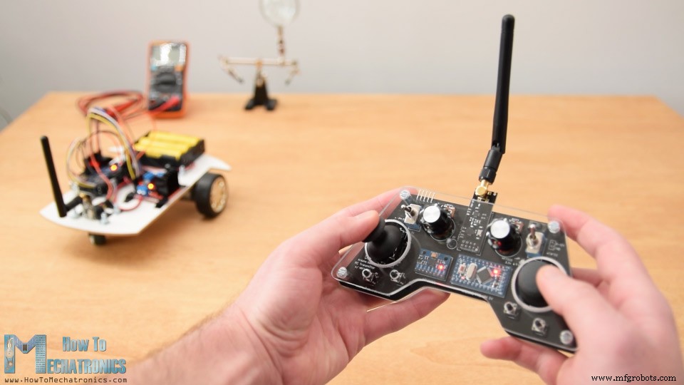
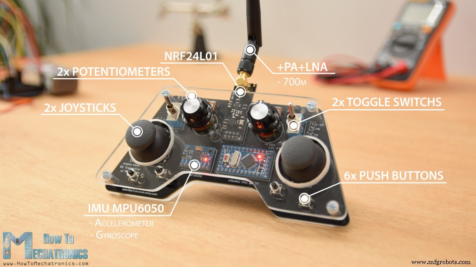
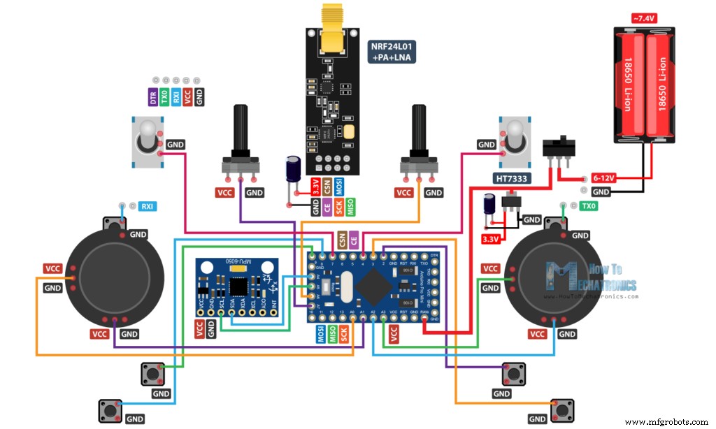
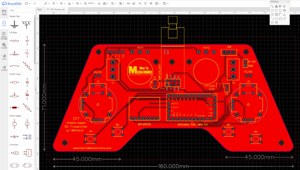
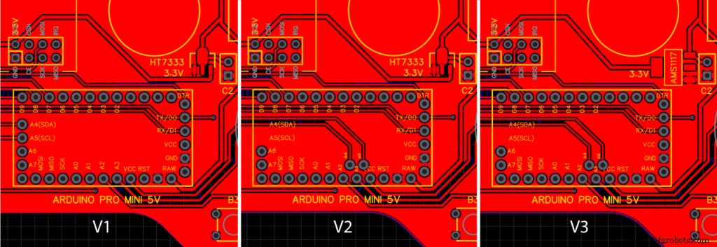
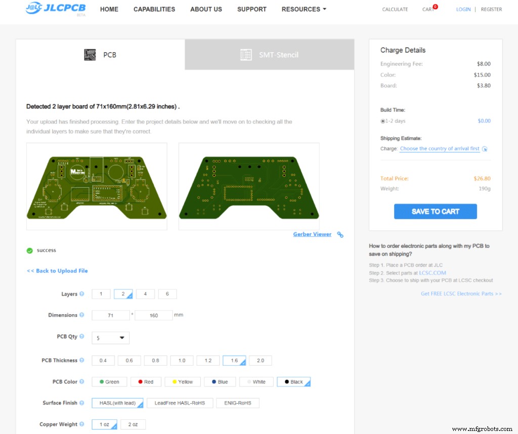
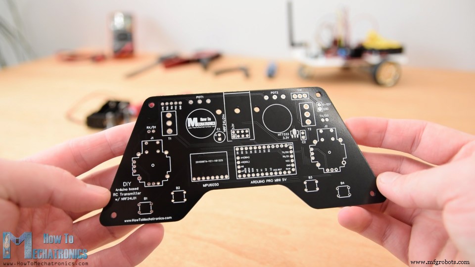
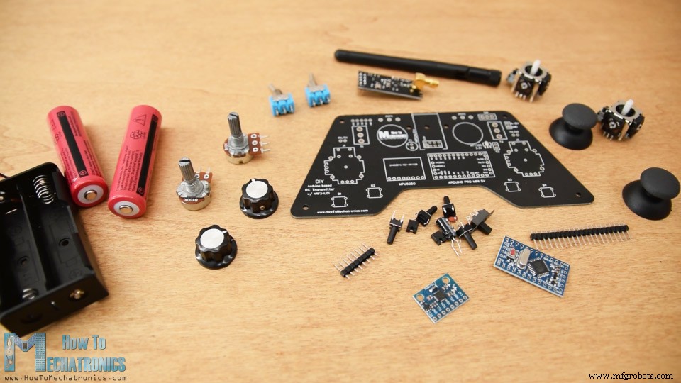
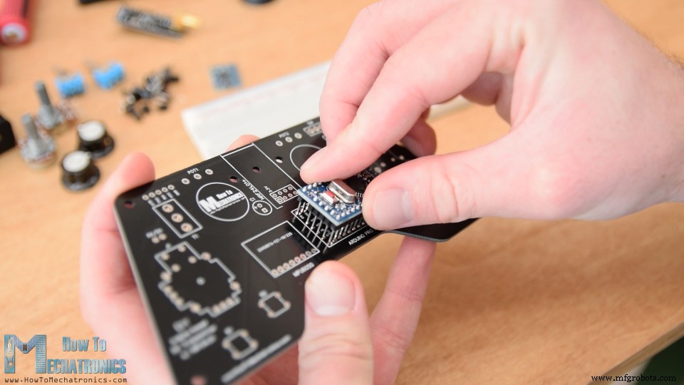
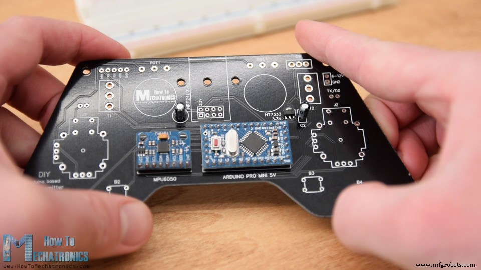
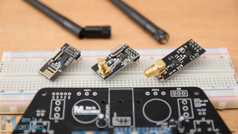
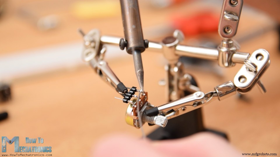
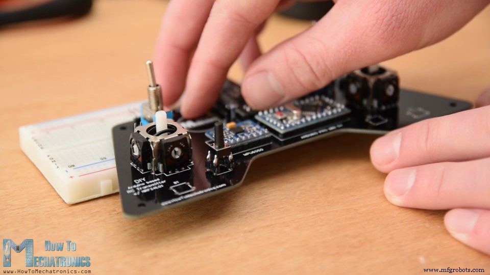
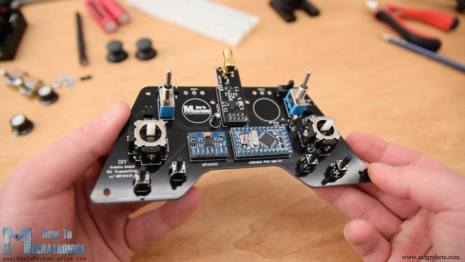
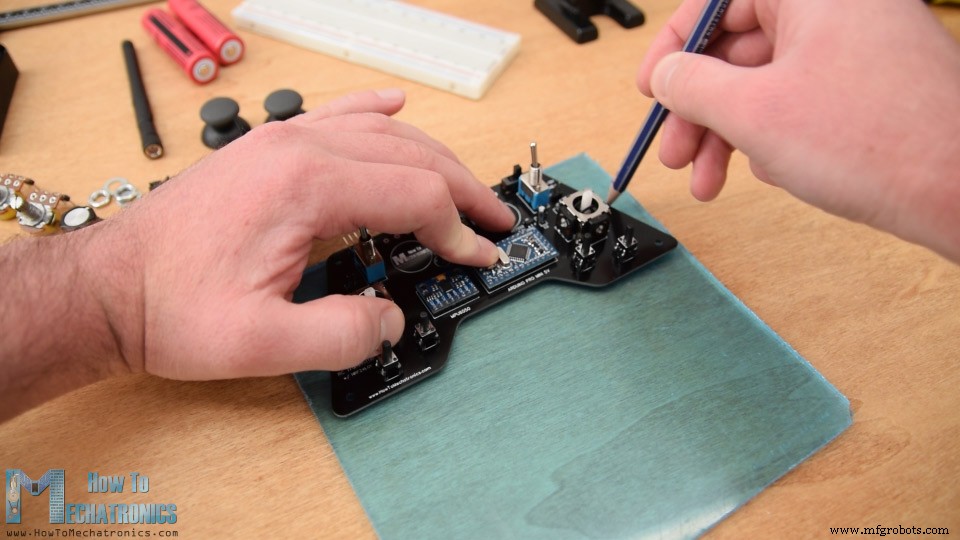
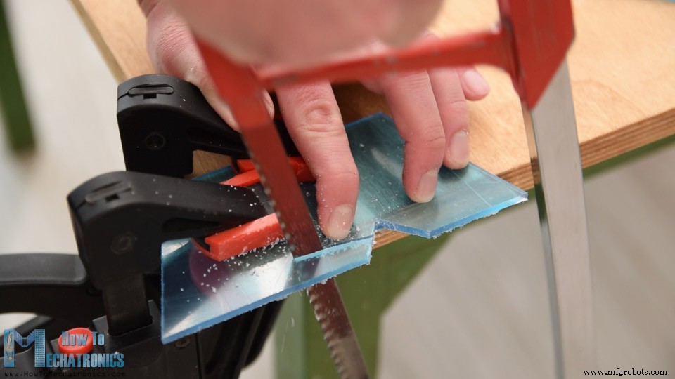
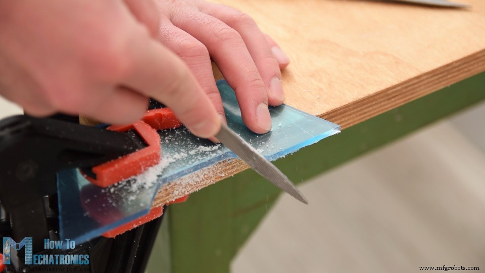
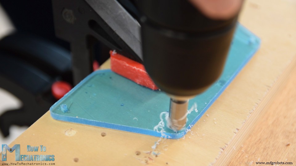
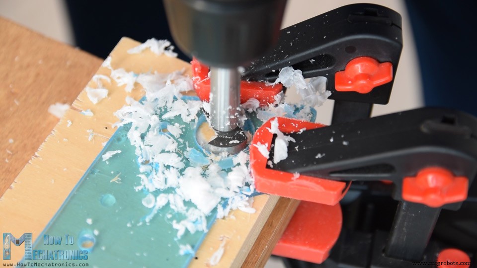
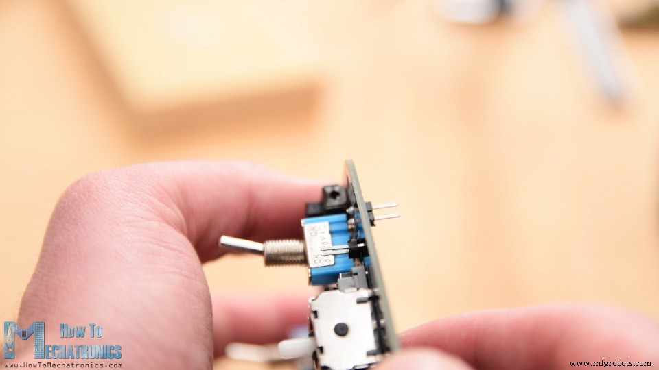
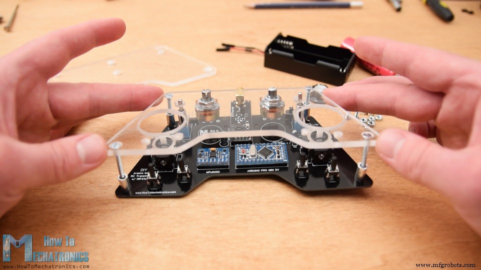
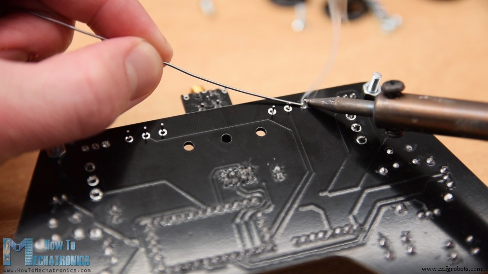
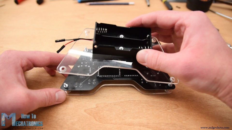
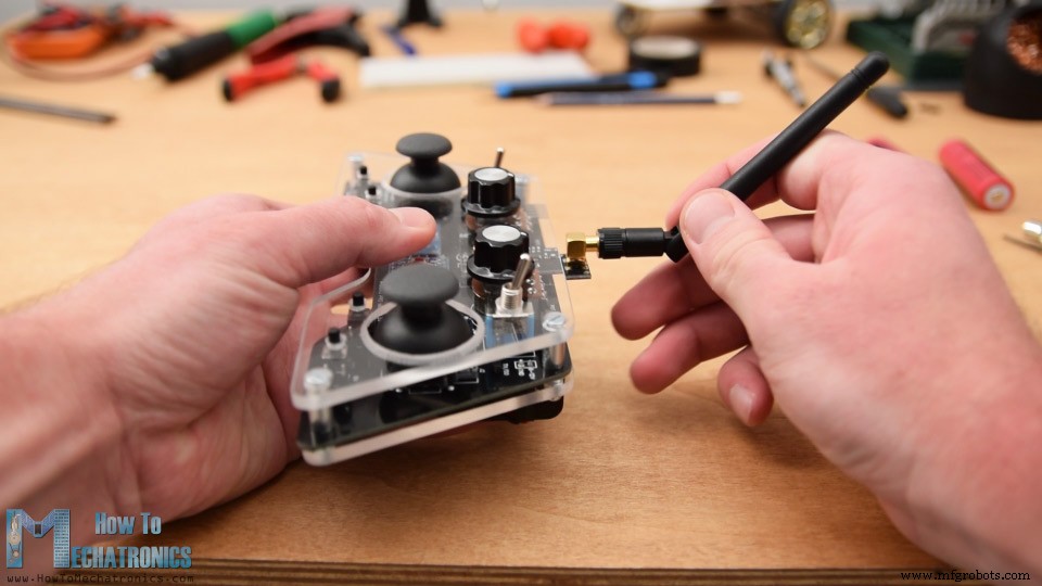
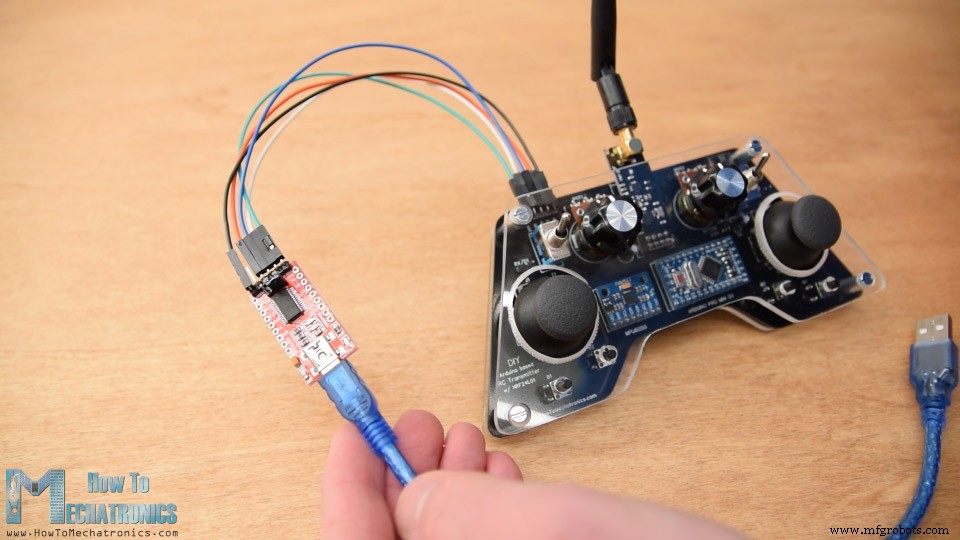
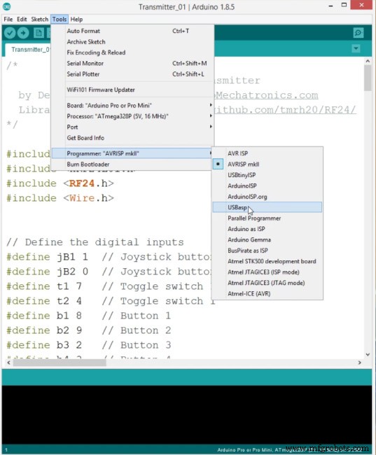
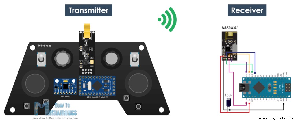
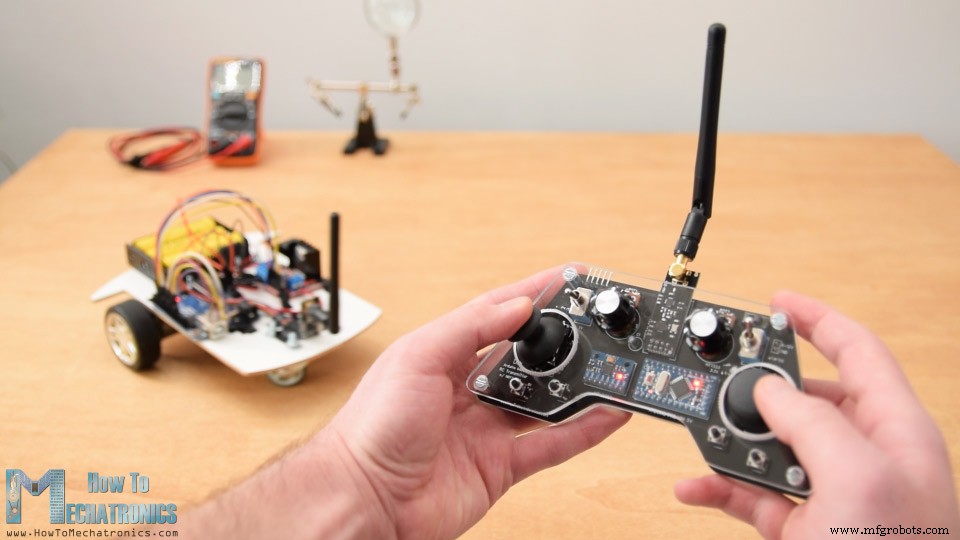
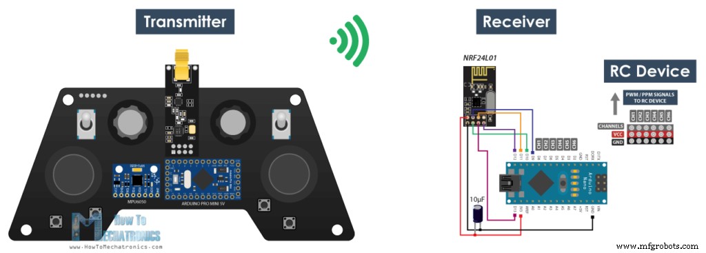
In tutorial we will learn how to build a DIY Arduino RC transmitter. Very often I need wireless control for the projects that I make, so therefore I built this multifunctional radio controller which can be used for pretty much everything. You can watch the following video or read the written tutorial below. Now I can wirelessly control any Arduino project with just some small adjustments at the receiver side. This transmitter can be also used as any commercial RC transmitter for controlling RC toys, cars, drones and so on. For that purpose it just needs a simple Arduino receiver which then generates the appropriate signals for controlling those commercial RC devices. I will explain how everything works in this video through few examples of controlling an Arduino robot car, controlling the Arduino Ant Robot from my previous video and controlling a brushless DC motor using an ESC and some servo motors. The radio communication of this controller is based on the NRF24L01 transceiver module which if used with an amplified antenna it can have a stable range of up to 700 meters in open space. It features 14 channels, 6 of which are analog inputs and 8 digital inputs. It has two joysticks, two potentiometers, two toggle switches, six buttons and additionally an internal measuring unit consisting of an accelerometer and a gyroscope which can be also used for controlling things with just moving around or tilting the controller. To begin with, let’s take a look at the circuit diagram. The brain of this RC controller is an Arduino Pro Mini which is powered using 2 LiPo batteries producing around 7.4 volts. We can connect them directly to the RAW pin of the Pro Mini which has a voltage regulator that reduced the voltage to 5V. Note that there are two versions of the Arduino Pro Mini, like the one I have that operates at 5V and the other operates at 3.3V. On the other hand, the NRF24L01 module strictly needs 3.3V and it’s recommended to come from a dedicated source. Therefore we need to use a 3.3V voltage regulator which is connected to the batteries and convert the 7.4V to 3.3V. Also we need to use a decoupling capacitor right next to the module in order to keep the voltage more stable, thus the radio communication will be more stable as well. The NRF24L01 module communicates with the Arduino using SPI protocol, while the MPU6050 accelerometer and gyro module uses the I2C protocol. You can get the components needed for this Arduino Tutorial from the links below: I actually ended up utilizing all analog and digital pins of the Arduino Pro Mini. So now if I try to connect everything together using jump wires it will be quite a mess. Therefore I designed a custom PCB using the EasyEDA free online circuit design software. Here I took into consideration the ergonomics of the controller and designed it to be easily held by two hands, while all controls are within the range of the fingers. I made the edges round and added some 3mm holes so I can mount the PCB onto something later. I placed the pins for programming the Arduino Pro Mini at the top side of the controller so they can be easily accessed in case we want to reprogram the Arduino. We can also notice here that I used the RX and TX pins of the Arduino for the joystick buttons. However these two lines needs to be disconnected from anything while we are uploading the sketch to the Arduino. So therefore they are interrupted with two pins which can be then easily connected using simple jumper caps. Please note: Make sure you have the right Arduino Pro Mini version to mach the PCB or modify the PCB design according to it. Here’s a comparison photo between the three different versions, depending on your Arduino and the voltage regulator. Here’s a link to the project files of this PCB design. These opens the three different version in separate tabs, so you can choose the one you need. So once I finished the design, I generated the Gerber file needed for manufacturing the PCB. Gerber file: Then I ordered the PCB from JLCPCB which are also the sponsor of this video. Here we can simply drag and drop the Gerber file and once uploaded, we can review our PCB in the Gerber viewer. If everything is all right then we can go on and select the properties that we want for our PCB. This time I chose the PCB color to be black. And that’s it, now we can simply order our PCB at a reasonable price. Note that if it’s your first order from JLCPCB, you can get up to 10 PCBs for only $2. And here it is. I just really love how this PCB turned out in this black color. The quality of the PCB is great, and everything is exactly the same as in the design. Ok now we can move on with assembling the PCB. I started with a soldering the pin headers of the Arduino Pro Mini. An easy and good way to do that is to place them onto a breadboard and so they will stay firmly in place while soldering. The Pro Mini also have pins on the sides, but note that these pins location might vary depending on the manufacturer. For the particular model that I have, I need 5 pins for each side, while leaving one GND pin empty because I used its area below on the PCB for running some traces. I soldered the Arduino Pro Mini directly onto the PCB and cut the execs length of the headers. Right next to it goes the MPU6050 accelerometer and gyroscope module. Then I soldered the 3.3V voltage regulator with a capacitor next to it, and another capacitor near the NRF24L01 module. This module have three different versions and we can use any of them here. I continued with the pins for programming the Arduino, the RX and TX pins, the power supply pins and the power switch. Next for soldering the potentiometers to the PCB I had to extend their pins using some pin headers. We can note here that I previously cut the length of the knobs so I can properly fit some caps onto them. However, we will solder the potentiometers to the PCB a bit later. Then I inserted and soldered the two toggle switches and the two joysticks in place. Finally what’s left is to solder the four push buttons. However they don’t have the proper height, so again I used pin headers to extend their pins a little bit. And that’s it, our PCB is now ready so we can continue with making the cover for it. Because I like how the PCB looks and I want to be visible I decided to use transparent acrylic for the cover. Here I have 4 mm tick transparent acrylic which currently have a protective foil and appears to be blue. The idea for the cover is to make two plates with the shape of the PCB and secure one of them at the top side and the other at the bottom side of the PCB. So I marked PCB shape and using a metal hand saw I cut the acrylic according to it. Then using a simple rasp I fine-tuned the shape of the acrylic. The two plates came out great and they perfectly match with the PCB. Next I marked the locations where I need to make openings for the components to pass through. Using a 3mm drill I first made the 4 holes for securing the plates to the PCB. For these holes I also made counter sinks so that the bolts can be placed flash with the plates. For the openings for the toggle switches and the potentiometers I used 6mm drill, and for the joystick openings I used 25mm Forstner bit. Again, using a rasp, I fine-tuned all the openings. Before assembling the cover, just a quite note that I actually soldered the pin header for the power supply upside down so it can be reached from the back side where the battery will be located. Ok now we can start with assembling the cover. I started with peeling off the protective foil from the acrylic which I must admit was quite satisfying because the acrylic was so clean now. So first I secured the two potentiometers on the top plate, inserted the 3mm mounting bolts and placed the 11mm distance rings in place. Then I carefully merged and secured the top plate and the PCB using some bolts. At this point I finally soldered the potentiometers to the PCB because earlier I didn’t know exactly at what height they will be placed. Next on the back plate I attached the battery holder using 2 bolts. I finished the cover assembly by securing the back plate to the back side of the PCB using the four mounting bolts. Finally, we can attach the battery lines to the power supply pins, insert and secure the knobs on the potentiometers, insert the joysticks knobs and attach the antenna to the NRF24l01 module. And that’s it, we are finally done with the DIY Arduino RC transmitter. What’s left now is to program the Arduino. For programming a Pro Mini board we need an USB to serial UART interface which can be hooked up to the programing header located on the top side of our controller. Then in the Arduino IDE tools menu we need to select the Arduino Pro or Pro Mini board, select the proper version of the processor, select the port and select the programming method to “USBasp”. And so now we are able to upload the code to the Arduino. Let’s explain how the transmitter code works. So first we need to include the SPI and RF24 library for the wireless communication, and the I2C library for the accelerometer module. Then we need to define the digital inputs, some variables needed for the program below, define the radio object and the communication address. Then we need to define a structure where we will store the 14 input values of the controller. The maximum size of this structure can be 32 bytes because that’s the NRF24L01 buffer limit or the amount of data the module can send at once. In the setup section we need to initialize the MPU6050 module and we can also calculate the IMU error which is a values that is later used when calculating the correct angles of the module. You can find more details how MEMS accelerometer and gyro work here. A dedicated tutorial for the MPU6050 is coming soon. Then we need to initialize the radio communication, activate the Arduino internal pull-up resistors for all digital inputs and set the initial default values for all variables. In the loop section start by reading the all analog inputs, map their values from 0 to 1023 into byte values from 0 to 255 because we already defined the variables in our structure as bytes. Each input is stored in the particular data variable from the structure. We should just note that because we use the pull-up resistors the digital pins readings are 0 when the buttons are pressed. So using the radio.write() function we simple send the values from all 14 channels to the receiver. In case the toggle switch 1 is switched on, then we use the accelerometer and gyro data instead for the control. So instead of the joystick 1 X and Y values we are using the angle values we are getting from the IMU, which we previously convert them from values from -90 to +90 degrees into byte values from 0 to 255 appropriately. So that’s how the transmitter code, the most important things were defining the radio communication and sending the data to the receiver. Here’s the complete Arduino code for this DIY Arduino RC Transmitter: Now let’s take a look at how we can receive this data. Here’s a simple Arduino and NRF24L01 receiver schematic. Of course you can use any other Arduino board. And here’s a simple receiver code where we will receive the data and simply print it on the serial monitor so that we know that the communication works properly. Again we need to include the RF24 library and define the objects and the structure the same way as in the transmitter code. In the setup section when defining the radio communication we need to use the same settings as the transmitter and set the module as receiver using the radio.startListening() function. In the main loop using the available() function we check whether there is an incoming data. If true we simply read the data and store it into the variables of the structure. Now we can print the data on the serial monitor to check whether the transmission work properly. Also using the millis() function and an if statement we check whether we keep receiving data, or if we don’t receive data for a period longer than 1 second, then we reset variables to their default values. We use this to prevent unwanted behavior, for example if a drone has a throttle up and we lose connection it can keep flying away unless we reset the values. So that’s it. Now we can implement this method of receiving the data for any Arduino project. For example here the code for controlling the Arduino robot car from one of my previous videos. As an update to this project, I made a dedicated Arduino based RC Receiver. Again, it’s based on the Arduino Pro mini board and it has several ready to use servos and ESCs connections, placed on a compact PCB. Arduino Code: Here we need to define the libraries, the structure and the radio communication as explained earlier. Then in the main loop we just need read the incoming data and use any of it for whatever we want. In this case I use the joystick 1 values for driving the car. Arduino Code: In the exact same way I made the Arduino Ant Robot from my previous video to be wirelessly controlled using this Arduino RC Transmitter. We just need to read the data, and according to it execute the appropriate functions, like moving forward, left, right, bite, attack and so on. Lastly, let’s take a look how can this transmitter be used for controlling commercial RC devices. Usually for these devices we need to control their servos or brushless motors. So after receiving the data from the transmitter, for controlling servo we simply use the Arduino Servo library and use values from 0 to 180 degrees. For controlling brushless motor using ESC, we can again use the servo library for generating the 50Hz PWM signal used for controlling the ESC. By varying the duty cycle from 1000 to 2000 microseconds we control the RPM of the motor from zero to maximum. However, more on controlling brushless motors using ESC in my next tutorial. Please note that we actually cannot bind the standard RC receiver system with this NRF24L01 2.4GHz system. Instead, we need to modify or create our own receiver consisting of an Arduino and NRF24L01 Module. From there we can than generate the appropriate PWM or PPM signals for controlling the RC device. So that’s it. I hope you enjoyed this video and learned something new. Feel free to ask any question in the comments section below and check my Arduino Projects Collection.Overview
Arduino RC Transmitter Circuit Diagram
PCB Design

Assembling the PCB
DIY Arduino based RC Transmitter Code
#include <SPI.h>
#include <nRF24L01.h>
#include <RF24.h>
#include <Wire.h>


// Define the digital inputs
#define jB1 1  // Joystick button 1
#define jB2 0  // Joystick button 2
#define t1 7   // Toggle switch 1
#define t2 4   // Toggle switch 1
#define b1 8   // Button 1
#define b2 9   // Button 2
#define b3 2   // Button 3
#define b4 3   // Button 4

const int MPU = 0x68; // MPU6050 I2C address
float AccX, AccY, AccZ;
float GyroX, GyroY, GyroZ;
float accAngleX, accAngleY, gyroAngleX, gyroAngleY;
float angleX, angleY;
float AccErrorX, AccErrorY, GyroErrorX, GyroErrorY;
float elapsedTime, currentTime, previousTime;
int c = 0;


RF24 radio(5, 6);   // nRF24L01 (CE, CSN)
const byte address[6] = "00001"; // AddressCode language: Arduino (arduino)/ Max size of this struct is 32 bytes - NRF24L01 buffer limit
struct Data_Package {
byte j1PotX;
byte j1PotY;
byte j1Button;
byte j2PotX;
byte j2PotY;
byte j2Button;
byte pot1;
byte pot2;
byte tSwitch1;
byte tSwitch2;
byte button1;
byte button2;
byte button3;
byte button4;
};
Data_Package data; //Create a variable with the above structureCode language: Arduino (arduino)void initialize_MPU6050() {
Wire.begin(); // Initialize comunication
Wire.beginTransmission(MPU); // Start communication with MPU6050 // MPU=0x68
Wire.write(0x6B); // Talk to the register 6B
Wire.write(0x00); // Make reset - place a 0 into the 6B register
Wire.endTransmission(true); //end the transmission
// Configure Accelerometer
Wire.beginTransmission(MPU);
Wire.write(0x1C); //Talk to the ACCEL_CONFIG register
Wire.write(0x10); //Set the register bits as 00010000 (+/- 8g full scale range)
Wire.endTransmission(true);
// Configure Gyro
Wire.beginTransmission(MPU);
Wire.write(0x1B); // Talk to the GYRO_CONFIG register (1B hex)
Wire.write(0x10); // Set the register bits as 00010000 (1000dps full scale)
Wire.endTransmission(true);
}Code language: Arduino (arduino)// Define the radio communication
radio.begin();
radio.openWritingPipe(address);
radio.setAutoAck(false);
radio.setDataRate(RF24_250KBPS);
radio.setPALevel(RF24_PA_LOW);
// Activate the Arduino internal pull-up resistors
pinMode(jB1, INPUT_PULLUP);
pinMode(jB2, INPUT_PULLUP);
pinMode(t1, INPUT_PULLUP);
pinMode(t2, INPUT_PULLUP);
pinMode(b1, INPUT_PULLUP);
pinMode(b2, INPUT_PULLUP);
pinMode(b3, INPUT_PULLUP);
pinMode(b4, INPUT_PULLUP);Code language: Arduino (arduino)// Read all analog inputs and map them to one Byte value
data.j1PotX = map(analogRead(A1), 0, 1023, 0, 255); // Convert the analog read value from 0 to 1023 into a BYTE value from 0 to 255
data.j1PotY = map(analogRead(A0), 0, 1023, 0, 255);
data.j2PotX = map(analogRead(A2), 0, 1023, 0, 255);
data.j2PotY = map(analogRead(A3), 0, 1023, 0, 255);
data.pot1 = map(analogRead(A7), 0, 1023, 0, 255);
data.pot2 = map(analogRead(A6), 0, 1023, 0, 255);Code language: Arduino (arduino)// Read all digital inputs
data.j1Button = digitalRead(jB1);
data.j2Button = digitalRead(jB2);
data.tSwitch2 = digitalRead(t2);
data.button1 = digitalRead(b1);
data.button2 = digitalRead(b2);
data.button3 = digitalRead(b3);
data.button4 = digitalRead(b4);Code language: Arduino (arduino)// Send the whole data from the structure to the receiver
radio.write(&data, sizeof(Data_Package));Code language: Arduino (arduino)if (digitalRead(t1) == 0) {
read_IMU(); // Use MPU6050 instead of Joystick 1 for controling left, right, forward and backward movements
}Code language: Arduino (arduino)// Map the angle values from -90deg to +90 deg into values from 0 to 255, like the values we are getting from the Joystick
data.j1PotX = map(angleX, -90, +90, 255, 0);
data.j1PotY = map(angleY, -90, +90, 0, 255);Code language: Arduino (arduino)/*
DIY Arduino based RC Transmitter
by Dejan Nedelkovski, www.HowToMechatronics.com
Library: TMRh20/RF24, https://github.com/tmrh20/RF24/
*/
#include <SPI.h>
#include <nRF24L01.h>
#include <RF24.h>
#include <Wire.h>
// Define the digital inputs
#define jB1 1 // Joystick button 1
#define jB2 0 // Joystick button 2
#define t1 7 // Toggle switch 1
#define t2 4 // Toggle switch 1
#define b1 8 // Button 1
#define b2 9 // Button 2
#define b3 2 // Button 3
#define b4 3 // Button 4
const int MPU = 0x68; // MPU6050 I2C address
float AccX, AccY, AccZ;
float GyroX, GyroY, GyroZ;
float accAngleX, accAngleY, gyroAngleX, gyroAngleY;
float angleX, angleY;
float AccErrorX, AccErrorY, GyroErrorX, GyroErrorY;
float elapsedTime, currentTime, previousTime;
int c = 0;
RF24 radio(5, 6); // nRF24L01 (CE, CSN)
const byte address[6] = "00001"; // Address
// Max size of this struct is 32 bytes - NRF24L01 buffer limit
struct Data_Package {
byte j1PotX;
byte j1PotY;
byte j1Button;
byte j2PotX;
byte j2PotY;
byte j2Button;
byte pot1;
byte pot2;
byte tSwitch1;
byte tSwitch2;
byte button1;
byte button2;
byte button3;
byte button4;
};
Data_Package data; //Create a variable with the above structure
void setup() {
Serial.begin(9600);
// Initialize interface to the MPU6050
initialize_MPU6050();
// Call this function if you need to get the IMU error values for your module
//calculate_IMU_error();
// Define the radio communication
radio.begin();
radio.openWritingPipe(address);
radio.setAutoAck(false);
radio.setDataRate(RF24_250KBPS);
radio.setPALevel(RF24_PA_LOW);
// Activate the Arduino internal pull-up resistors
pinMode(jB1, INPUT_PULLUP);
pinMode(jB2, INPUT_PULLUP);
pinMode(t1, INPUT_PULLUP);
pinMode(t2, INPUT_PULLUP);
pinMode(b1, INPUT_PULLUP);
pinMode(b2, INPUT_PULLUP);
pinMode(b3, INPUT_PULLUP);
pinMode(b4, INPUT_PULLUP);
// Set initial default values
data.j1PotX = 127; // Values from 0 to 255. When Joystick is in resting position, the value is in the middle, or 127. We actually map the pot value from 0 to 1023 to 0 to 255 because that's one BYTE value
data.j1PotY = 127;
data.j2PotX = 127;
data.j2PotY = 127;
data.j1Button = 1;
data.j2Button = 1;
data.pot1 = 1;
data.pot2 = 1;
data.tSwitch1 = 1;
data.tSwitch2 = 1;
data.button1 = 1;
data.button2 = 1;
data.button3 = 1;
data.button4 = 1;
}
void loop() {
// Read all analog inputs and map them to one Byte value
data.j1PotX = map(analogRead(A1), 0, 1023, 0, 255); // Convert the analog read value from 0 to 1023 into a BYTE value from 0 to 255
data.j1PotY = map(analogRead(A0), 0, 1023, 0, 255);
data.j2PotX = map(analogRead(A2), 0, 1023, 0, 255);
data.j2PotY = map(analogRead(A3), 0, 1023, 0, 255);
data.pot1 = map(analogRead(A7), 0, 1023, 0, 255);
data.pot2 = map(analogRead(A6), 0, 1023, 0, 255);
// Read all digital inputs
data.j1Button = digitalRead(jB1);
data.j2Button = digitalRead(jB2);
data.tSwitch2 = digitalRead(t2);
data.button1 = digitalRead(b1);
data.button2 = digitalRead(b2);
data.button3 = digitalRead(b3);
data.button4 = digitalRead(b4);
// If toggle switch 1 is switched on
if (digitalRead(t1) == 0) {
read_IMU(); // Use MPU6050 instead of Joystick 1 for controling left, right, forward and backward movements
}
// Send the whole data from the structure to the receiver
radio.write(&data, sizeof(Data_Package));
}
void initialize_MPU6050() {
Wire.begin(); // Initialize comunication
Wire.beginTransmission(MPU); // Start communication with MPU6050 // MPU=0x68
Wire.write(0x6B); // Talk to the register 6B
Wire.write(0x00); // Make reset - place a 0 into the 6B register
Wire.endTransmission(true); //end the transmission
// Configure Accelerometer
Wire.beginTransmission(MPU);
Wire.write(0x1C); //Talk to the ACCEL_CONFIG register
Wire.write(0x10); //Set the register bits as 00010000 (+/- 8g full scale range)
Wire.endTransmission(true);
// Configure Gyro
Wire.beginTransmission(MPU);
Wire.write(0x1B); // Talk to the GYRO_CONFIG register (1B hex)
Wire.write(0x10); // Set the register bits as 00010000 (1000dps full scale)
Wire.endTransmission(true);
}
void calculate_IMU_error() {
// We can call this funtion in the setup section to calculate the accelerometer and gury data error. From here we will get the error values used in the above equations printed on the Serial Monitor.
// Note that we should place the IMU flat in order to get the proper values, so that we then can the correct values
// Read accelerometer values 200 times
while (c < 200) {
Wire.beginTransmission(MPU);
Wire.write(0x3B);
Wire.endTransmission(false);
Wire.requestFrom(MPU, 6, true);
AccX = (Wire.read() << 8 | Wire.read()) / 4096.0 ;
AccY = (Wire.read() << 8 | Wire.read()) / 4096.0 ;
AccZ = (Wire.read() << 8 | Wire.read()) / 4096.0 ;
// Sum all readings
AccErrorX = AccErrorX + ((atan((AccY) / sqrt(pow((AccX), 2) + pow((AccZ), 2))) * 180 / PI));
AccErrorY = AccErrorY + ((atan(-1 * (AccX) / sqrt(pow((AccY), 2) + pow((AccZ), 2))) * 180 / PI));
c++;
}
//Divide the sum by 200 to get the error value
AccErrorX = AccErrorX / 200;
AccErrorY = AccErrorY / 200;
c = 0;
// Read gyro values 200 times
while (c < 200) {
Wire.beginTransmission(MPU);
Wire.write(0x43);
Wire.endTransmission(false);
Wire.requestFrom(MPU, 4, true);
GyroX = Wire.read() << 8 | Wire.read();
GyroY = Wire.read() << 8 | Wire.read();
// Sum all readings
GyroErrorX = GyroErrorX + (GyroX / 32.8);
GyroErrorY = GyroErrorY + (GyroY / 32.8);
c++;
}
//Divide the sum by 200 to get the error value
GyroErrorX = GyroErrorX / 200;
GyroErrorY = GyroErrorY / 200;
// Print the error values on the Serial Monitor
Serial.print("AccErrorX: ");
Serial.println(AccErrorX);
Serial.print("AccErrorY: ");
Serial.println(AccErrorY);
Serial.print("GyroErrorX: ");
Serial.println(GyroErrorX);
Serial.print("GyroErrorY: ");
Serial.println(GyroErrorY);
}
void read_IMU() {
// === Read acceleromter data === //
Wire.beginTransmission(MPU);
Wire.write(0x3B); // Start with register 0x3B (ACCEL_XOUT_H)
Wire.endTransmission(false);
Wire.requestFrom(MPU, 6, true); // Read 6 registers total, each axis value is stored in 2 registers
//For a range of +-8g, we need to divide the raw values by 4096, according to the datasheet
AccX = (Wire.read() << 8 | Wire.read()) / 4096.0; // X-axis value
AccY = (Wire.read() << 8 | Wire.read()) / 4096.0; // Y-axis value
AccZ = (Wire.read() << 8 | Wire.read()) / 4096.0; // Z-axis value
// Calculating angle values using
accAngleX = (atan(AccY / sqrt(pow(AccX, 2) + pow(AccZ, 2))) * 180 / PI) + 1.15; // AccErrorX ~(-1.15) See the calculate_IMU_error()custom function for more details
accAngleY = (atan(-1 * AccX / sqrt(pow(AccY, 2) + pow(AccZ, 2))) * 180 / PI) - 0.52; // AccErrorX ~(0.5)
// === Read gyro data === //
previousTime = currentTime; // Previous time is stored before the actual time read
currentTime = millis(); // Current time actual time read
elapsedTime = (currentTime - previousTime) / 1000; // Divide by 1000 to get seconds
Wire.beginTransmission(MPU);
Wire.write(0x43); // Gyro data first register address 0x43
Wire.endTransmission(false);
Wire.requestFrom(MPU, 4, true); // Read 4 registers total, each axis value is stored in 2 registers
GyroX = (Wire.read() << 8 | Wire.read()) / 32.8; // For a 1000dps range we have to divide first the raw value by 32.8, according to the datasheet
GyroY = (Wire.read() << 8 | Wire.read()) / 32.8;
GyroX = GyroX + 1.85; //// GyroErrorX ~(-1.85)
GyroY = GyroY - 0.15; // GyroErrorY ~(0.15)
// Currently the raw values are in degrees per seconds, deg/s, so we need to multiply by sendonds (s) to get the angle in degrees
gyroAngleX = GyroX * elapsedTime;
gyroAngleY = GyroY * elapsedTime;
// Complementary filter - combine acceleromter and gyro angle values
angleX = 0.98 * (angleX + gyroAngleX) + 0.02 * accAngleX;
angleY = 0.98 * (angleY + gyroAngleY) + 0.02 * accAngleY;
// Map the angle values from -90deg to +90 deg into values from 0 to 255, like the values we are getting from the Joystick
data.j1PotX = map(angleX, -90, +90, 255, 0);
data.j1PotY = map(angleY, -90, +90, 0, 255);
}Code language: Arduino (arduino)Receiver Code
/*
    DIY Arduino based RC Transmitter Project
              == Receiver Code ==

  by Dejan Nedelkovski, www.HowToMechatronics.com
  Library: TMRh20/RF24, https://github.com/tmrh20/RF24/
*/
#include <SPI.h>
#include <nRF24L01.h>
#include <RF24.h>
RF24 radio(10, 9);   // nRF24L01 (CE, CSN)
const byte address[6] = "00001";

unsigned long lastReceiveTime = 0;
unsigned long currentTime = 0;

// Max size of this struct is 32 bytes - NRF24L01 buffer limit
struct Data_Package {
  byte j1PotX;
  byte j1PotY;
  byte j1Button;
  byte j2PotX;
  byte j2PotY;
  byte j2Button;
  byte pot1;
  byte pot2;
  byte tSwitch1;
  byte tSwitch2;
  byte button1;
  byte button2;
  byte button3;
  byte button4;
};

Data_Package data; //Create a variable with the above structure

void setup() {
  Serial.begin(9600);
  radio.begin();
  radio.openReadingPipe(0, address);
  radio.setAutoAck(false);
  radio.setDataRate(RF24_250KBPS);
  radio.setPALevel(RF24_PA_LOW);
  radio.startListening(); //  Set the module as receiver
  resetData();
}
void loop() {
  // Check whether there is data to be received
  if (radio.available()) {
    radio.read(&data, sizeof(Data_Package)); // Read the whole data and store it into the 'data' structure
    lastReceiveTime = millis(); // At this moment we have received the data
  }
  // Check whether we keep receving data, or we have a connection between the two modules
  currentTime = millis();
  if ( currentTime - lastReceiveTime > 1000 ) { // If current time is more then 1 second since we have recived the last data, that means we have lost connection
    resetData(); // If connection is lost, reset the data. It prevents unwanted behavior, for example if a drone has a throttle up and we lose connection, it can keep flying unless we reset the values
  }
  // Print the data in the Serial Monitor
  Serial.print("j1PotX: ");
  Serial.print(data.j1PotX);
  Serial.print("; j1PotY: ");
  Serial.print(data.j1PotY);
  Serial.print("; button1: ");
  Serial.print(data.button1);
  Serial.print("; j2PotX: ");
  Serial.println(data.j2PotX);
}

void resetData() {
  // Reset the values when there is no radio connection - Set initial default values
  data.j1PotX = 127;
  data.j1PotY = 127;
  data.j2PotX = 127;
  data.j2PotY = 127;
  data.j1Button = 1;
  data.j2Button = 1;
  data.pot1 = 1;
  data.pot2 = 1;
  data.tSwitch1 = 1;
  data.tSwitch2 = 1;
  data.button1 = 1;
  data.button2 = 1;
  data.button3 = 1;
  data.button4 = 1;
}Code language: Arduino (arduino)Arduino Robot Car Wireless Control using RC Transmitter
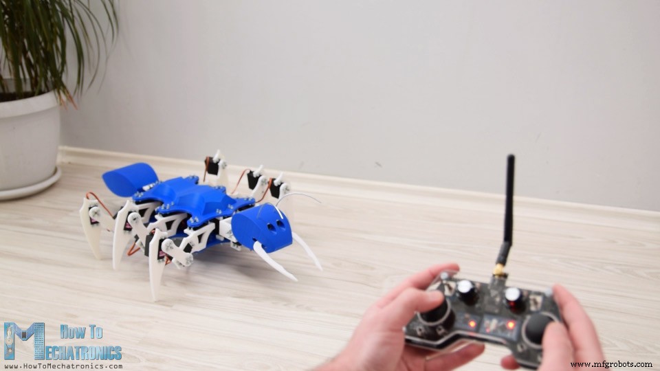
Arduino Ant Robot / Hexapod control using Arduino RC Transmitter
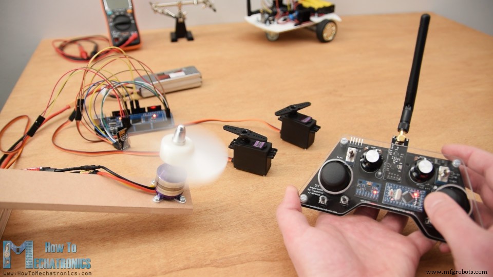
ESC and Servo Control using RC Transmitter
/*
    DIY Arduino based RC Transmitter Project
   == Receiver Code - ESC and Servo Control ==

  by Dejan Nedelkovski, www.HowToMechatronics.com
  Library: TMRh20/RF24, https://github.com/tmrh20/RF24/
*/
#include <SPI.h>
#include <nRF24L01.h>
#include <RF24.h>
#include <Servo.h>

RF24 radio(10, 9);   // nRF24L01 (CE, CSN)
const byte address[6] = "00001";

unsigned long lastReceiveTime = 0;
unsigned long currentTime = 0;

Servo esc;  // create servo object to control the ESC
Servo servo1;
Servo servo2;
int escValue, servo1Value, servo2Value;

// Max size of this struct is 32 bytes - NRF24L01 buffer limit
struct Data_Package {
  byte j1PotX;
  byte j1PotY;
  byte j1Button;
  byte j2PotX;
  byte j2PotY;
  byte j2Button;
  byte pot1;
  byte pot2;
  byte tSwitch1;
  byte tSwitch2;
  byte button1;
  byte button2;
  byte button3;
  byte button4;
};

Data_Package data; //Create a variable with the above structure

void setup() {
  Serial.begin(9600);
  radio.begin();
  radio.openReadingPipe(0, address);
  radio.setAutoAck(false);
  radio.setDataRate(RF24_250KBPS);
  radio.setPALevel(RF24_PA_LOW);
  radio.startListening(); //  Set the module as receiver
  resetData();
  esc.attach(9);
  servo1.attach(3);
  servo2.attach(4);
}
void loop() {
  // Check whether we keep receving data, or we have a connection between the two modules
  currentTime = millis();
  if ( currentTime - lastReceiveTime > 1000 ) { // If current time is more then 1 second since we have recived the last data, that means we have lost connection
    resetData(); // If connection is lost, reset the data. It prevents unwanted behavior, for example if a drone jas a throttle up, if we lose connection it can keep flying away if we dont reset the function
  }
  // Check whether there is data to be received
  if (radio.available()) {
    radio.read(&data, sizeof(Data_Package)); // Read the whole data and store it into the 'data' structure
    lastReceiveTime = millis(); // At this moment we have received the data
  }
  // Controlling servos
  servo1Value = map(data.j2PotX, 0, 255, 0, 180);
  servo2Value = map(data.j2PotY, 0, 255, 0, 180);
  servo1.write(servo1Value);
  servo2.write(servo2Value);
  // Controlling brushless motor with ESC
  escValue = map(data.pot1, 0, 255, 1000, 2000); // Map the receiving value form 0 to 255 to 0 1000 to 2000, values used for controlling ESCs
  esc.writeMicroseconds(escValue); // Send the PWM control singal to the ESC
}

void resetData() {
  // Reset the values when there is no radio connection - Set initial default values
  data.j1PotX = 127;
  data.j1PotY = 127;
  data.j2PotX = 127;
  data.j2PotY = 127;
  data.j1Button = 1;
  data.j2Button = 1;
  data.pot1 = 1;
  data.pot2 = 1;
  data.tSwitch1 = 1;
  data.tSwitch2 = 1;
  data.button1 = 1;
  data.button2 = 1;
  data.button3 = 1;
  data.button4 = 1;
}Code language: Arduino (arduino)
Manufacturing process
- Build a Smart Voltmeter with Arduino & Smartphone – Easy DIY Project
- Compact Weather Station: Arduino Nano & ESP8266 with BMP280 Barometric Sensor & OLED/Nokia LCD Display
- Build a DIY VR Skateboard with Arduino, Google Cardboard, and Bluetooth
- Build a DIY Arduino Radionics EMR Treatment Device
- DIY 2D Motion Racing Simulator Using Arduino Nano & SG90 Servos
- Build a Portable RFID Door Lock with Arduino – Step-by-Step Guide
- DIY Arduino Height Measurement Device – Accurate & Easy to Build
- Create an AM Music Transmitter Using Arduino Nano
- Build a Complete Arduino‑Powered RC Airplane from Scratch
- Build an Arduino‑Powered RC Hovercraft: Full 3D‑Printed Design & Programming Guide