


Create an AM Music Transmitter Using Arduino Nano
Components and supplies
 |
| × | 1 | |||
 |
| × | 2 | |||
 |
| × | 1 | |||
 |
| × | 1 |
Apps and online services
 |
|
About this project
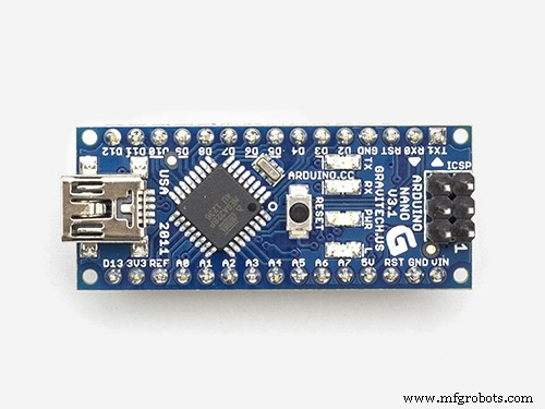
Cool things can be done with ATmega MCUs. So I got the idea to build an AM transmitter with an Arduino Nano (any other Arduino is also possible)
The question is, how can amplitude modulation (AM) be achieved on a digital device? AM means that the amplitude of a carrier frequency is changed according to the amplitude of the input signal which we want to transmit. Mathematically spoken, we multiply the carrier with the input signal. But as an ATmega has only digital outputs, it can give only two values: high and low. Frankly spoken, there is no way to get real AM out of an Arduino.
Nevertheless it is possible to produce some output signal that can be heard clearly with an ordinary AM radio receiver!
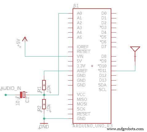
The solution consists of transforming the analog input signal into a PWM signal, using the ADC and the 16-bit timer/counter1 of the ATmega MCU.
The timer/counter2 generates the carrier signal, which can be varied in a wide range between 31KHz and 8MHz.
This carrier signal is output on pin D11 in the rhythm of the PWM signal. The AM radio behaves like a low pass filter on the PWM, so we get back the original audio signal there.
This is only a proof of concept, so I kept it simple. If you really want to use this as RF transmitter, you should add a low-pass fillter for anti-aliasing to the audio input and a low pass against the harmonics to the RF output.
Code
- Arduino AM Transmitter
Arduino AM TransmitterC/C++
/*This work is licensed under the Creative Commons Attribution-ShareAlike 4.0 International License. To view a copy of this license, visit http://creativecommons.org/licenses/by-sa/4.0/.*/

#define ANTENNA_PIN PB3 //Arduino Nano/Uno D11

// the setup function runs once when you press reset or power the board
void setup() {
	Serial.begin(115200);

	//Carrier Frequency generation
	uint32_t fTransmit = 600; //KHz
	DDRB |= (1 << ANTENNA_PIN);
	TCCR2A = (0 << COM2A1) + (1 << COM2A0); //Toggle OC0A on Compare Match
	TCCR2A |= (1 << WGM21) + (0 << WGM20); //CTC
	TCCR2B = (0 << CS22) + (0 << CS21) + (1 << CS20); //No Prescaling
	OCR2A = F_CPU / (2000 * fTransmit) - 1;

	char strbuf[255];
	sprintf(strbuf, "Will broadcast at %d KHz", (F_CPU / (2 * (1 + OCR2A)) / 1000));
	Serial.println(strbuf);

	//PWM Signal generation
	//TCCR1A |= (0 << WGM11) + (1 << WGM10);  //Fast PWM 8 Bit
	//TCCR1A |= (1 << WGM11) + (0 << WGM10);  //Fast PWM 9 Bit
	TCCR1A |= (1 << WGM11) + (1 << WGM10); //Fast PWM 10 Bit
	TCCR1B = (1 << WGM12);
	TCCR1B |= (0 << CS12) + (0 << CS11) + (1 << CS10); //No Prescaling
	TIMSK1 = (1 << OCIE1A) + (1 << TOIE1);

	//ADC Settings
	ADMUX = (1 << REFS1) + (1 << REFS0); //Reference internal 1.1V
	ADCSRA = (1 << ADEN) + (1 << ADSC) + (1 << ADATE); //Auto Trigger enable, free running
	ADCSRA |= (1 << ADPS2) + (1 << ADPS1) + (0 << ADPS0); //Divide by 64 -> 18.5k Sample rate
	DIDR0 = (1 << ADC0D);
}

ISR(TIMER1_OVF_vect) {
	uint8_t adcl = ADCL;
	uint8_t adch = ADCH;
	OCR1A = (adch << 8) + adcl;
	DDRB |= (1 << ANTENNA_PIN);
}

ISR(TIMER1_COMPA_vect) {
	DDRB &= ~(1 << ANTENNA_PIN);
}

void loop() {
}
Schematics
Manufacturing process
- Build Your Own LUMAZOID: A DIY Arduino Music Visualizer
- Decode RC Receiver PPM Signals with Arduino: A Step‑by‑Step Guide
- Using a Thermistor Made Easy: Step‑by‑Step Arduino Guide
- Create Musical Tones with Arduino: A Step‑by‑Step Guide
- Connecting Arduino to NMEA‑0183: A Step‑by‑Step Guide
- Master Modbus on Arduino: Step‑by‑Step Guide
- Control Your Robot with Brainwaves: A Comprehensive Arduino Project
- Master Rotary Encoders with Arduino: How They Work & Step‑by‑Step Integration
- Build a Multifunctional Arduino RC Transmitter: Step‑by‑Step DIY Guide
- Arduino SD Card 101: Setup, Connection, and Usage Guide