


Master Modbus on Arduino: Step‑by‑Step Guide
Components and supplies
 |
| × | 1 | |||
| × | 1 | ||||
| × | 1 | ||||
 |
| × | 1 | |||
 |
| × | 1 | |||
 |
| × | 1 | |||
 |
| × | 1 | |||
 |
| × | 1 | |||
 |
| × | 1 |
Apps and online services
 |
| |||
|
About this project
Modbus, a serial communication standard, has become a de facto standard communication protocol and is now a commonly available means of connecting industrial electronic devices. In Modbus RTU and Modbus ASCII, RS485 is used as the physical layer. It's possible to use an Arduino as slave (and with some restrictions also as master) in Modbus applications, but a RS485 interface is needed. Our RS422 / RS485 Shield is a fully galvanic isolated serial communication shield designed for use with the Arduino UNO and other compatible boards like Arduino 101, STM Nucleo... This shield the perfect choice for such kind of applications.
The objective of this document is to show how to create together with an Arduino UNO a simple Modbus slave device. We will use a PC as Modbus master.
Tools & Materials
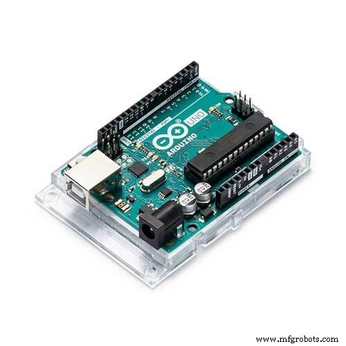
- Arduino UNO
- RS485 Shield for Arduino
- Any RS485-USB-Adapter for PC connection (or a cheaper one)
Optional:
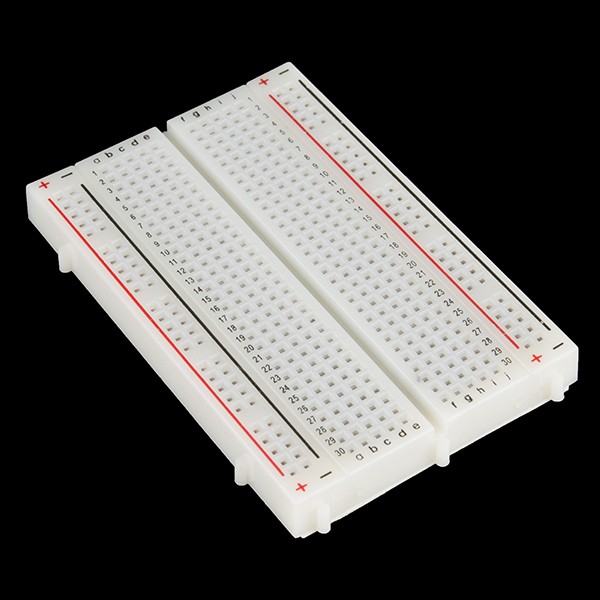
- Breadboard
- Push button
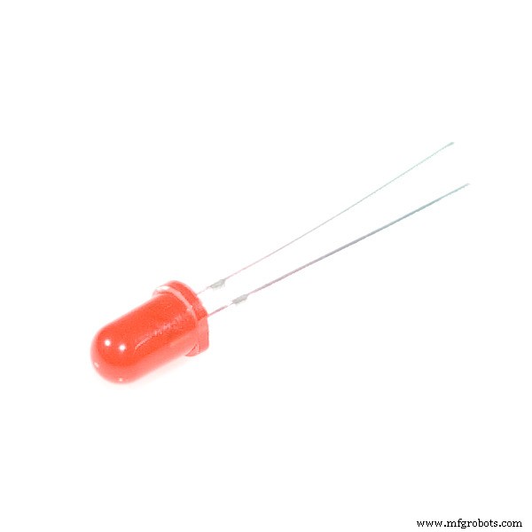
- Red LED
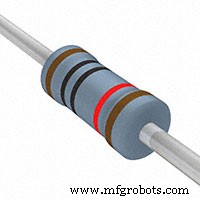
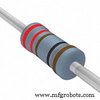
- 220 Ohm Resistor
- 10k Resistor
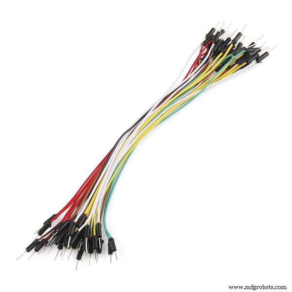
- Jumper wires
Software
- Arduino IDE
- Modbustester
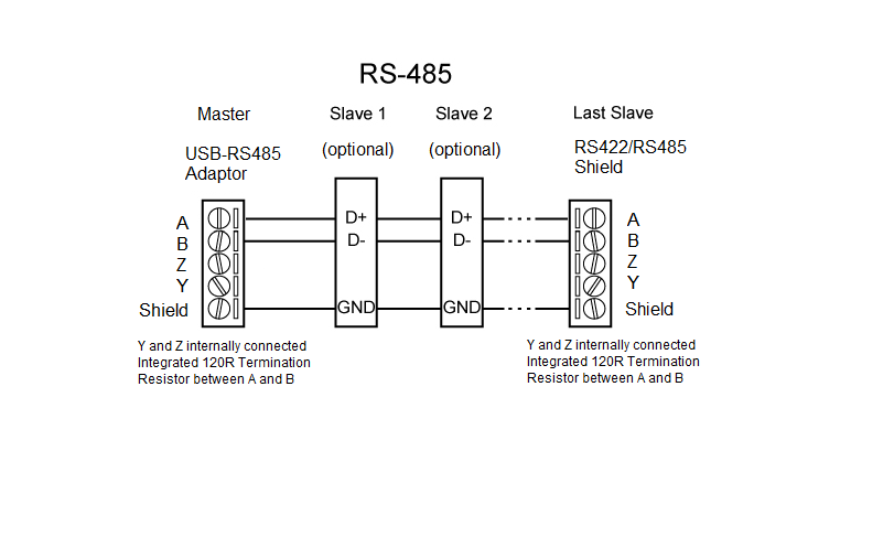
The wiring is very simple. You have to connect only the A and B terminals of the shield with the A and B line of the Modbus system. Y and Z terminals are not used for this kind of application. For long distances it is recommend to use twisted pairs for A and B.
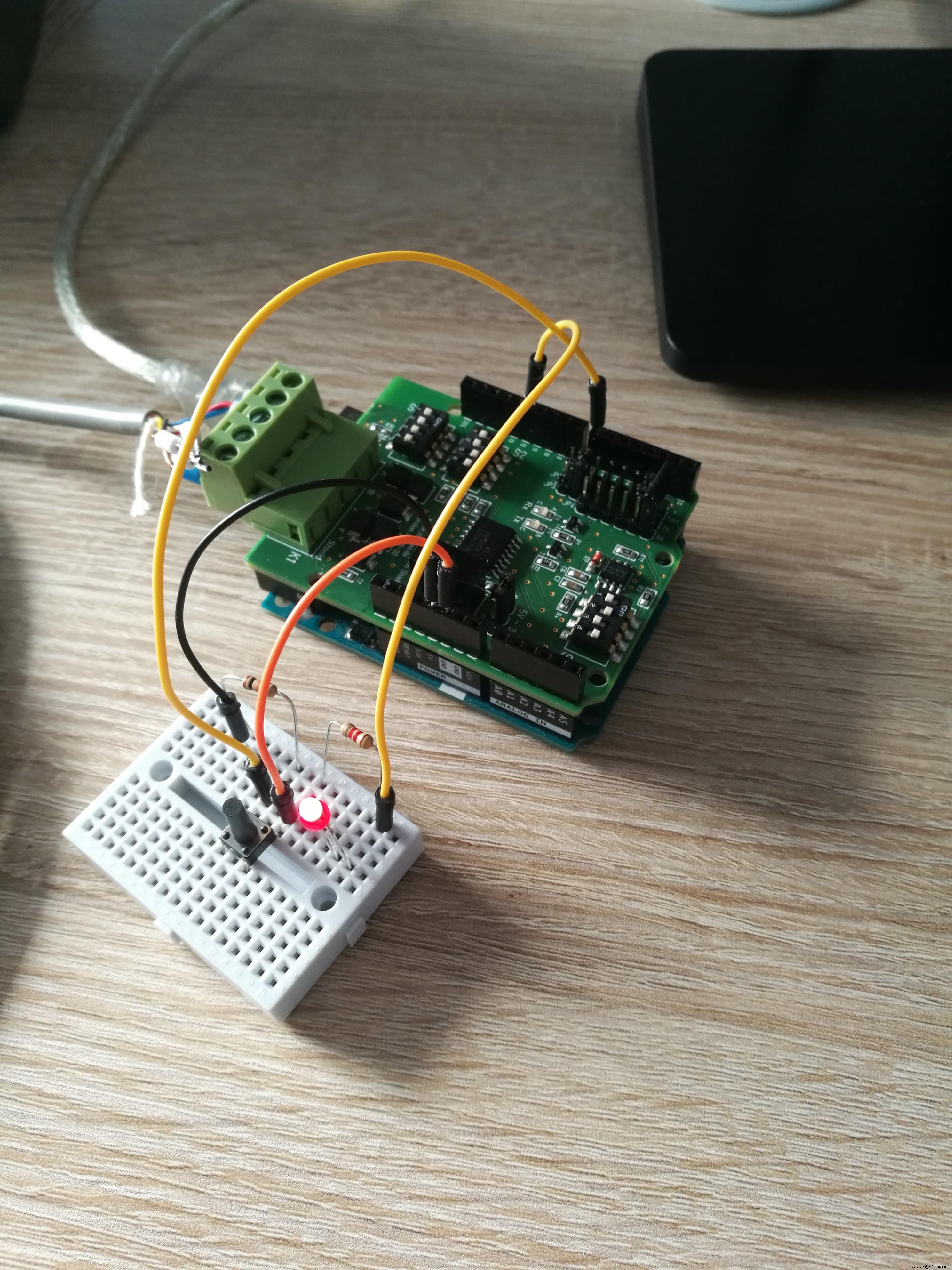
Wiring Arduino (Optional):It's recommend to add a LED and a button to the Arduino to see some effects of the Modbus communication. It's optional and not necessary needed.
The RS422/RS485 Shield comes with 3 DIP switch banks. You have to set these DIP switches for Modbus as shown in the picture below.
Switch 1:1-OFF 2-ON 3-ON 4-OFF
Switch 2: 1-OFF 2-OFF 3-ON 4-ON
Switch 3: 1-OFF or ON* 2-OFF 3-OFF 4-OFF
*Depending of the position of the RS422/RS485 Shield in the Modbus line you have to switch the terminating resistor ON or OFF. Please switch the resistor to ON position only if the Shield is on one end of the bus line. In all other cases switch the terminating resistor OFF:
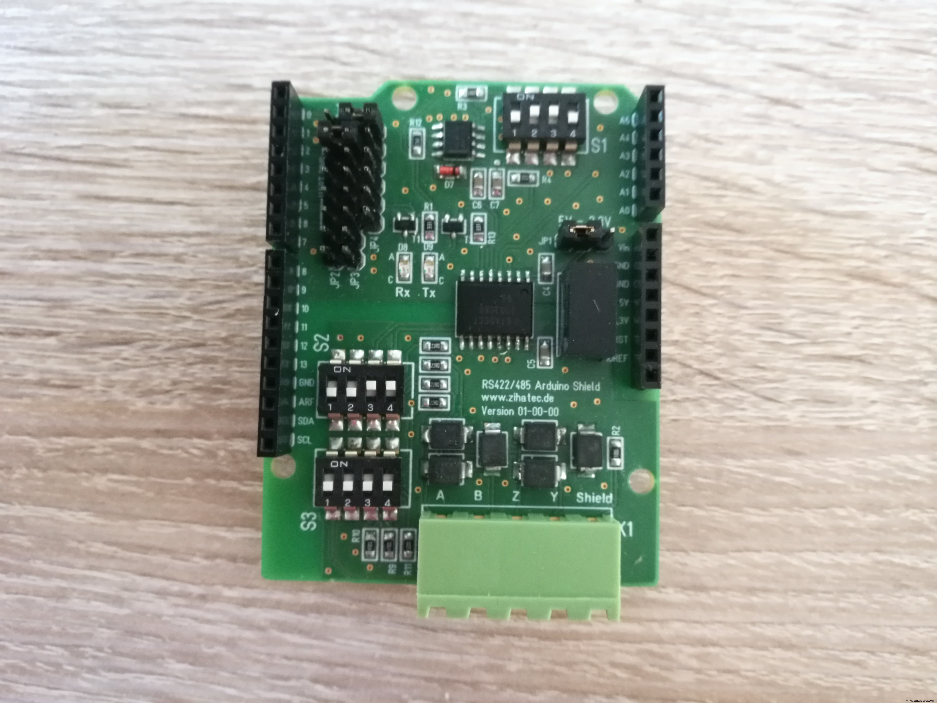
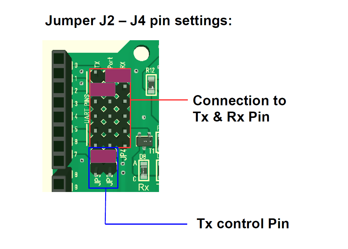
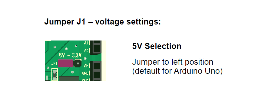
You can find 3 different jumper areas on the shield. Very important is the Jumper JP1 for the power supply voltage. The Arduino UNO works with 5V internally. You have to set this Jumper to the 5V position (for 3.3V boards for example Arduino 101 to the 3.3V position).
Furthermore set the jumpers for the communication ports in the upper left corner as in the picture above. The internal UART on port 0 and 1 will be connected in this case to the RS485 interface of the shield.
Last but not least we have to set Jumper for the RX/TX control port.We don't use this Jumper, because the automatic RX/TX switching is configured.
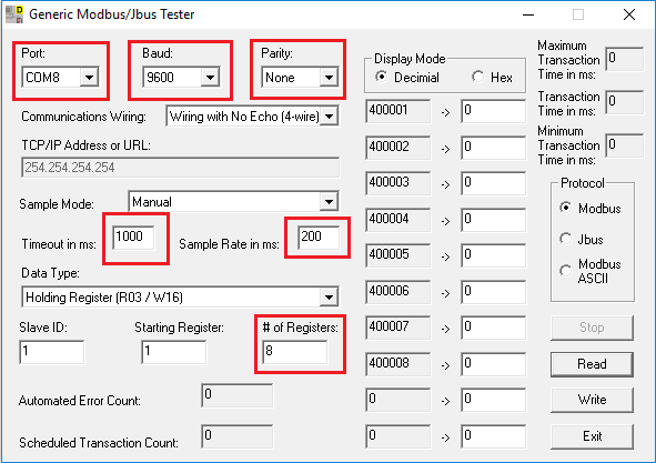
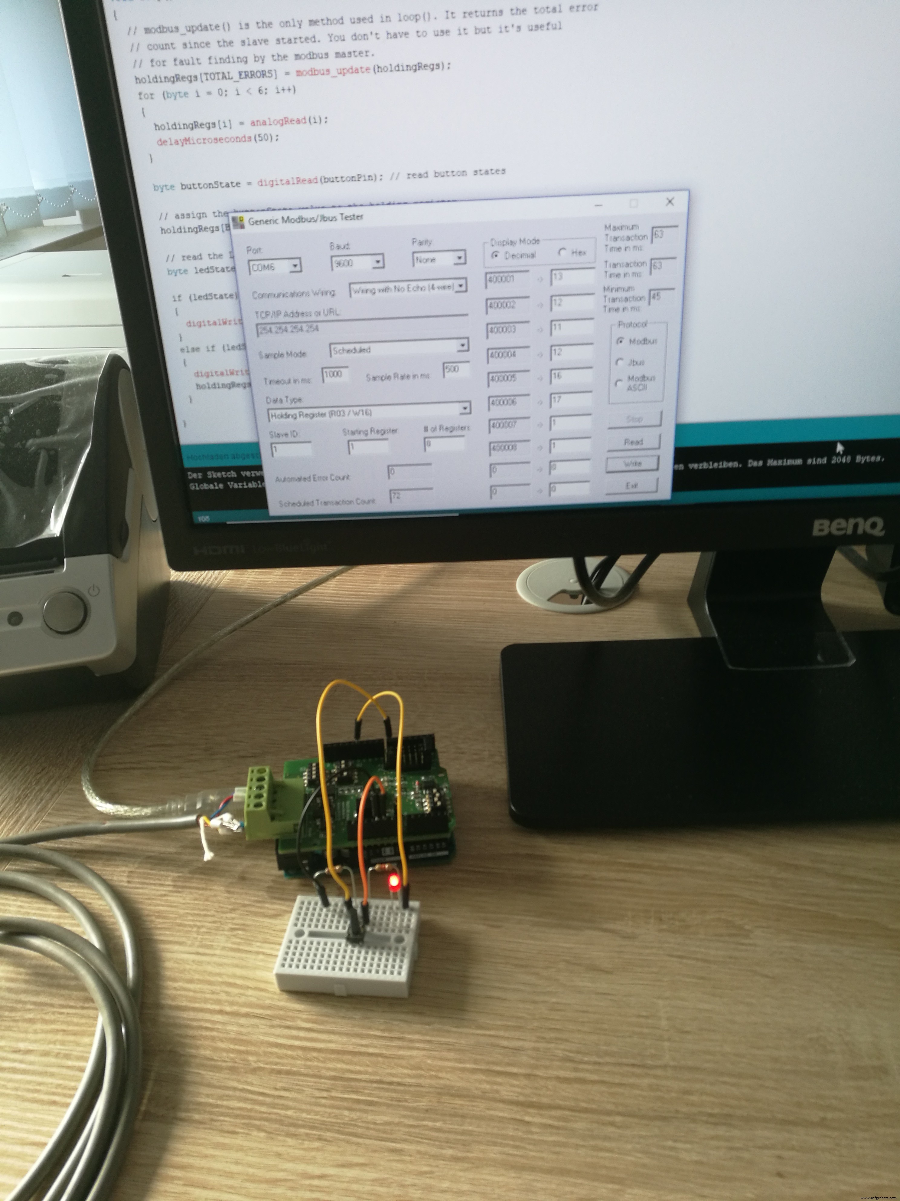
We will use in this example the PC as Modbus master. You've to download Modbustester. Please unpack the zip archive to a new directory on your harddisk. Open the software and change the marked fields as in the picture below. You have to connect the USB-RS485-adaptor bevore- Please choose the right COM-port for this adaptor in Modbustester.
Please load the firmware into the Arduino IDE for compiling and programming.
Test Your Work:Now its time to test your work!
You can press the Read button in Modbustester. This command will read 8 bytes of the memory of our new slave device. In address 400008 you can find the status of the button. The address 400001 - 400006 contains values of the ADC ports.
With the write button you can manipulate registers in the slave. You can enter in address 400007 a 0 or 1 to switch the LED ON or OFF.
Code
- Sample code for Arduino UNO
Sample code for Arduino UNOArduino
/*
 *  Test program for Arduino RS422/RS485 Shield
 *  Version 1.0
 *  Copyright (C) 2018  Hartmut Wendt  www.zihatec.de
 *
 *  (based on sources of https://github.com/angeloc/simplemodbusng)
 *
 *
 *  This program is free software: you can redistribute it and/or modify
 *  it under the terms of the GNU General Public License as published by
 *  the Free Software Foundation, either version 3 of the License, or
 *  (at your option) any later version.
 *
 *  This program is distributed in the hope that it will be useful,
 *  but WITHOUT ANY WARRANTY; without even the implied warranty of
 *  MERCHANTABILITY or FITNESS FOR A PARTICULAR PURPOSE.  See the
 *  GNU General Public License for more details.
 *
 *  You should have received a copy of the GNU General Public License
 *  along with this program.  If not, see <http://www.gnu.org/licenses/>.
*/

#include <SimpleModbusSlave.h>

#define  ledPin  12 // onboard led
#define  buttonPin  7 // push button


/* This example code has 9 holding registers. 6 analogue inputs, 1 button, 1 digital output
   and 1 register to indicate errors encountered since started.
   Function 5 (write single coil) is not implemented so I'm using a whole register
   and function 16 to set the onboard Led on the Atmega328P.

   The modbus_update() method updates the holdingRegs register array and checks communication.

   Note:
   The Arduino serial ring buffer is 128 bytes or 64 registers.
   Most of the time you will connect the arduino to a master via serial
   using a MAX485 or similar.

   In a function 3 request the master will attempt to read from your
   slave and since 5 bytes is already used for ID, FUNCTION, NO OF BYTES
   and two BYTES CRC the master can only request 122 bytes or 61 registers.

   In a function 16 request the master will attempt to write to your
   slave and since a 9 bytes is already used for ID, FUNCTION, ADDRESS,
   NO OF REGISTERS, NO OF BYTES and two BYTES CRC the master can only write
   118 bytes or 59 registers.

   Using the FTDI USB to Serial converter the maximum bytes you can send is limited
   to its internal buffer which is 60 bytes or 30 unsigned int registers.

   Thus:

   In a function 3 request the master will attempt to read from your
   slave and since 5 bytes is already used for ID, FUNCTION, NO OF BYTES
   and two BYTES CRC the master can only request 54 bytes or 27 registers.

   In a function 16 request the master will attempt to write to your
   slave and since a 9 bytes is already used for ID, FUNCTION, ADDRESS,
   NO OF REGISTERS, NO OF BYTES and two BYTES CRC the master can only write
   50 bytes or 25 registers.

   Since it is assumed that you will mostly use the Arduino to connect to a
   master without using a USB to Serial converter the internal buffer is set
   the same as the Arduino Serial ring buffer which is 128 bytes.
*/


// Using the enum instruction allows for an easy method for adding and
// removing registers. Doing it this way saves you #defining the size
// of your slaves register array each time you want to add more registers
// and at a glimpse informs you of your slaves register layout.

//////////////// registers of your slave ///////////////////
enum
{
  // just add or remove registers and your good to go...
  // The first register starts at address 0
  ADC0,
  ADC1,
  ADC2,
  ADC3,
  ADC4,
  ADC5,
  LED_STATE,
  BUTTON_STATE,
  TOTAL_ERRORS,
  // leave this one
  TOTAL_REGS_SIZE
  // total number of registers for function 3 and 16 share the same register array
};

unsigned int holdingRegs[TOTAL_REGS_SIZE]; // function 3 and 16 register array
////////////////////////////////////////////////////////////

void setup()
{
  /* parameters(long baudrate,
                unsigned char ID,
                unsigned char transmit enable pin,
                unsigned int holding registers size,
                unsigned char low latency)

     The transmit enable pin is used in half duplex communication to activate a MAX485 or similar
     to deactivate this mode use any value < 2 because 0 & 1 is reserved for Rx & Tx.
     Low latency delays makes the implementation non-standard
     but practically it works with all major modbus master implementations.
  */

  modbus_configure(9600, 1, 6, TOTAL_REGS_SIZE, 0);
  pinMode(ledPin, OUTPUT);
  pinMode(buttonPin, INPUT);

}

void loop()
{
  // modbus_update() is the only method used in loop(). It returns the total error
  // count since the slave started. You don't have to use it but it's useful
  // for fault finding by the modbus master.
  holdingRegs[TOTAL_ERRORS] = modbus_update(holdingRegs);
  for (byte i = 0; i < 6; i++)
  {
    holdingRegs[i] = analogRead(i);
    delayMicroseconds(50);
  }

  byte buttonState = digitalRead(buttonPin); // read button states

  // assign the buttonState value to the holding register
  holdingRegs[BUTTON_STATE] = buttonState;

  // read the LED_STATE register value and set the onboard LED high or low with function 16
  byte ledState = holdingRegs[LED_STATE];

  if (ledState) // set led
  {
    digitalWrite(ledPin, HIGH);
  }
  else if (ledState == 0) // reset led
  {
    //digitalWrite(ledPin, LOW);
    holdingRegs[LED_STATE] = 0;
  }

}
Schematics
Wiring of some test components to the Arduino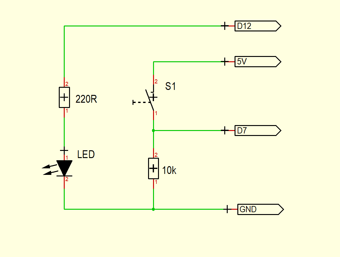
Manufacturing process
- Build a Real-Time Gyroscope Game with Arduino Nano & MPU-6050 Sensor
- Unopad: Seamless Arduino MIDI Controller for Ableton Live
- Build a Simple Obstacle Sensor with Arduino – Easy IR LED & Photodiode Tutorial
- Using a Thermistor Made Easy: Step‑by‑Step Arduino Guide
- Create Musical Tones with Arduino: A Step‑by‑Step Guide
- Connecting Arduino to NMEA‑0183: A Step‑by‑Step Guide
- Master Rotary Encoders with Arduino: How They Work & Step‑by‑Step Integration
- PIR Motion Sensor: Working Principles & Arduino Integration Guide
- Mastering RGB LEDs with Arduino: A Step-by-Step Tutorial
- Master the 28BYJ-48 Stepper Motor: A Complete Arduino Integration Guide