


Using a Transistor as an Electrically Controlled Switch
PARTS AND MATERIALS
- Two 6‑V batteries
- One NPN transistor (2N2222 or 2N3403 recommended; Radio Shack catalog #276‑1617 offers a pack of fifteen)
- One 100 kΩ resistor
- One 560 Ω resistor
- One LED (Radio Shack catalog #276‑026 or any standard LED)
Resistor values and the specific LED type are not critical for the demonstration.
CROSS‑REFERENCES
Lessons In Electric Circuits, Volume 3, Chapter 4: “Bipolar Junction Transistors.”
LEARNING OBJECTIVES
- Understand current amplification in a bipolar junction transistor.
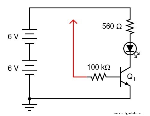
SCHEMATIC DIAGRAM
ILLUSTRATION
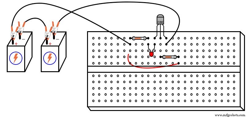
INSTRUCTIONS
The diagram shows a red wire that terminates in an arrowhead and connects to one end of the 100 kΩ resistor. Leave this wire loose so you can touch it briefly to other points in the circuit.
Touch the free end of the red wire to any point that is more positive than it—most commonly the positive terminal of the DC supply. The LED will illuminate even though the 100 kΩ resistor limits current to only about 0.12 mA (12 V ÷ 100 kΩ). This illustrates how a small base current can control a much larger collector current.
To quantify the effect, use an ammeter in series with the red wire and connect it to the positive supply:
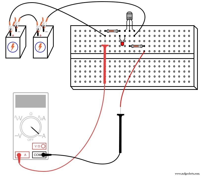
Choose the most sensitive range on the meter to read the tiny base current. Then measure the LED current and compare the two values. You will typically find a current gain greater than 200, confirming the transistor’s role as an electrically controlled switch.
For a hands‑on demonstration, remove the loose wire and try bridging the unconnected end of the 100 kΩ resistor to the supply’s positive pole with two fingers. Wetting the fingertips can improve conductivity. Vary the pressure of your contact to change the resistance in the base path; observe how the LED brightness changes. This shows the transistor’s ability to act as a variable current controller, not just a binary switch.
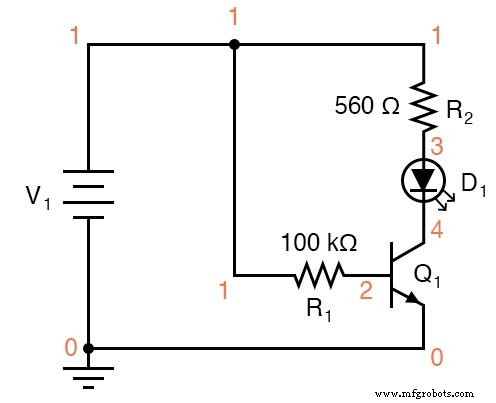
COMPUTER SIMULATION
Schematic with SPICE node numbers:
Netlist (copy the following text into a .cir file):
Transistor as a switch v1 1 0 r1 1 2 100k r2 1 3 560 d1 3 4 mod2 q1 4 2 0 mod1 .model mod1 npn bf=200 .model mod2 d is=1e-28 .dc v1 12 12 1 .print dc v(2,0) v(4,0) v(1,2) v(1,3) v(3,4) .end
Simulation results: The voltage drop across the 560 Ω resistor (v(1,3)) is 10.26 V, corresponding to an LED current of 18.32 mA. The 100 kΩ resistor experiences a drop of 11.15 V, yielding only 111.5 µA of base current—highlighting the transistor’s amplification capability.
The diode model parameter is=1e-28 simulates an LED’s higher forward voltage drop.
RELATED WORKSHEET
- Bipolar Junction Transistors as Switches Worksheet
Industrial Technology
- Hands‑On Guide to Current Dividers: Build, Measure, and Simulate with a 6 V Battery
- Sensitive Static‑Electricity Detector Using a JFET Switch
- Bipolar Junction Transistors (BJT): Core Principles and Practical Applications
- BJT Switching: How Transistors Efficiently Control High‑Current Loads
- Precision Transistor Biasing: Calculating Resistors for Stable Amplifier Performance
- Using a Junction Field‑Effect Transistor (JFET) as a Low‑Power On/Off Switch
- Insulated‑Gate Bipolar Transistors (IGBTs): Merging FET Precision with BJT Power
- Understanding the Shockley Diode: A Comprehensive Guide to PNPN Thyristors
- Silicon‑Controlled Switch (SCS): Design, Operation, and Forced Commutation
- Understanding Six Primary Leakage Mechanisms in MOS Transistors