


Sensitive Static‑Electricity Detector Using a JFET Switch
PARTS AND MATERIALS
- One N‑channel junction field‑effect transistor (JFET), such as the 2N3819 or J309 (Radio Shack catalog #276‑2035).
- One 6‑V battery.
- One 100 kΩ resistor.
- One light‑emitting diode (LED) (Radio Shack catalog #276‑026 or equivalent).
- Plastic comb.
The specific JFET model is flexible; P‑channel devices can also be used, though N‑channel transistors are more common.
Transistor pinouts vary even among visually identical packages. Always consult the datasheet for accurate pin assignments. Double‑check pin identities with a multimeter’s diode‑check function to avoid wiring errors.
For detailed guidance on identifying JFET terminals with a multimeter, see chapter 5 of the Semiconductor Volume III series.
CROSS‑REFERENCES Lessons In Electric Circuits, Volume 3, Chapter 5: “Junction Field‑Effect Transistors.”
LEARNING OBJECTIVES
- Understand how a JFET functions as an on/off switch.
- Compare JFET current gain with that of a bipolar transistor.
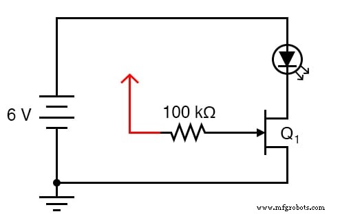
SCHEMATIC DIAGRAM
ILLUSTRATION
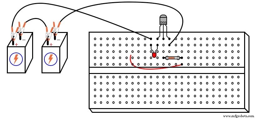
INSTRUCTIONS
Building this circuit is straightforward, mirroring the earlier BJT switch experiment but replacing the bipolar device with a JFET. The result is a far more sensitive static‑electricity detector.
After assembly, touch the free wire end (the red wire in the schematic and illustration) that is connected to the 100 kΩ resistor with your hand. Even a brief touch should alter the LED’s state.
For a more pronounced effect, walk across a carpet to build up static charge, then touch the wire. If no change occurs, gently scuff your feet to increase the charge.
A controlled test involves touching the wire with one hand while alternately tapping the battery’s positive (+) and negative (–) terminals with a finger of the other hand. Your body serves as a conductor, linking the JFET gate to one of the battery terminals as you switch contacts.
Note which terminal turns the LED on and which turns it off. Relate this behavior to the JFET characteristics discussed in chapter 5 of the Semiconductor volume.
The ease with which a JFET can be switched—requiring minimal control current—highlights its superior current‑gain capability compared to the BJT switch. The JFET’s gate requires only a tiny voltage change, often achievable through the static charge of your body.
Because JFETs can be turned on and off from a distance by static fields, try brushing your hair with a plastic comb and waving the comb near the transistor. The resulting high‑voltage field should be detected by the circuit, visibly affecting the LED.
Many small‑signal JFETs, such as the 2N3819, self‑limit the drain current (I_DSS) to about 10 mA (max 20 mA). Since most LEDs are rated for a forward current of 20 mA, no additional series resistor is needed; the JFET naturally limits the current to a safe level.
Industrial Technology
- Using a Transistor as an Electrically Controlled Switch
- Bipolar Junction Transistors (BJT): Core Principles and Practical Applications
- BJT Switching: How Transistors Efficiently Control High‑Current Loads
- Precision Transistor Biasing: Calculating Resistors for Stable Amplifier Performance
- Insulated‑Gate Bipolar Transistors (IGBTs): Merging FET Precision with BJT Power
- Understanding the Shockley Diode: A Comprehensive Guide to PNPN Thyristors
- Static Electricity Explained: How Rubbing Materials Generates Charge
- Understanding the Physiological Impact of Electrical Shock
- Understanding Six Primary Leakage Mechanisms in MOS Transistors
- ACS712 Current Sensor: A Comprehensive Guide for Accurate Current Measurement