


BJT Switching: How Transistors Efficiently Control High‑Current Loads
Bipolar Junction Transistors (BJTs) are versatile components that can function as amplifiers, filters, rectifiers, oscillators, and, importantly, switches. When biased into the linear region, a BJT behaves as an amplifier; when biased into saturation or cutoff, it acts as a power switch, allowing or blocking current flow in other parts of the circuit.
A BJT’s collector current is governed by its base current, enabling it to serve as a current‑controlled switch. A modest current injected into the base can control a much larger collector current, making the transistor an ideal solution for high‑current applications.
Using a BJT as a Switch: A Practical Example
Consider a simple lamp that we want to turn on and off. The classic approach uses a mechanical switch, as shown in figure (a). By replacing the switch with a transistor, we can illustrate how a BJT controls the lamp’s current. The collector and emitter must replace the switch contacts, and the lamp’s current must flow opposite to the emitter arrow to maintain proper junction bias, as depicted in figure (b).
(a) Mechanical switch; (b) NPN transistor switch; (c) PNP transistor switch.
A PNP transistor could equally perform this task, shown in figure (c). The choice between NPN and PNP is arbitrary—what matters is correct current direction to preserve junction bias (electron flow opposite the transistor symbol’s arrow).
In the diagrams above, the transistor’s base is left floating, so no base current flows and the device remains off. A practical solution is to insert a small switch between the base and the collector, as illustrated below.
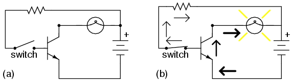
Transistor states: (a) Cutoff—lamp off; (b) Saturated—lamp on.
Cutoff vs. Saturation
When the switch is open (figure a), the base is floating and no current flows; the transistor is in cutoff mode, fully non‑conducting. When the switch is closed (figure b), base current flows from base to emitter, enabling a large collector‑to‑emitter current that lights the lamp. In this state, the transistor is in saturation mode, fully conducting.
At first glance, replacing a mechanical switch with a transistor may seem unnecessary. However, the transistor offers significant advantages in certain scenarios.
Why Use a Transistor for Current Control?
Two key benefits:
- Low‑current control—The switch contacts only need to handle the small base current required to turn the transistor on, allowing a small switch to control a high‑current load.
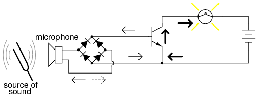
- Remote or alternative control signals—The transistor’s base can be driven by virtually any DC source, enabling control via solar cells, thermocouples, microphones, or other sensors.
For example, a pair of solar cells can provide 1 V to overcome the transistor’s 0.7 V base‑emitter drop, initiating base current and turning on the lamp. Similarly, multiple thermocouples in series can supply the necessary voltage, and an amplified microphone signal—rectified to DC—can also bias the base.
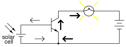
Solar cells serve as a light sensor to trigger the transistor.
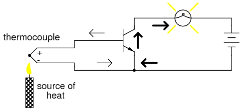
Thermocouples in series generate >0.7 V to bias the base.
Rectified microphone output biases the base for light control.
In each case, the transistor acts as a true amplifier: a small DC control signal regulates a larger power supply that drives the lamp. The lamp’s actual power comes from the main battery; the control signals merely govern its operation.
BJT as a Switch – Quick Review
- Transistors can switch DC power to a load; the controlled current flows between emitter and collector, while the controlling base current flows between emitter and base.
- Zero base current puts the transistor in cutoff—nonconducting.
- Maximum base current drives the transistor into saturation—fully conducting.
Related Worksheet
- Bipolar Junction Transistors as Switches Worksheet
Industrial Technology
- Using a Transistor as an Electrically Controlled Switch
- Understanding the NOT Gate (Inverter) in TTL Circuits
- Understanding the PN Junction: From Structure to Diode Behavior
- Bipolar Junction Transistors (BJT): Core Principles and Practical Applications
- Common-Emitter Amplifier Limitations: Distortion, Temperature, and High‑Frequency Challenges
- Using a Junction Field‑Effect Transistor (JFET) as a Low‑Power On/Off Switch
- Insulated‑Gate Bipolar Transistors (IGBTs): Merging FET Precision with BJT Power
- Understanding the Shockley Diode: A Comprehensive Guide to PNPN Thyristors
- DIAC: The Bidirectional Trigger for AC Thyristors
- Silicon‑Controlled Switch (SCS): Design, Operation, and Forced Commutation