


Silicon‑Controlled Switch (SCS): Design, Operation, and Forced Commutation
Incorporating an additional external terminal into the classic SCR equivalent circuit yields the silicon‑controlled switch (SCS). The extra terminal, connected to the base of the upper transistor and the collector of the lower transistor, grants an extra degree of control, particularly enabling forced commutation when the device must be turned off before the current falls below the holding value.

The Silicon‑Controlled Switch (SCS)
When an external signal drives the SCS into the off state, it is called forced commutation. In the illustrated motor start/stop circuit, the motor resides in the anode‑gate loop. Though it may appear counterintuitive, the anode lead must be the switching point; therefore the motor cannot be placed in series with the anode terminal.
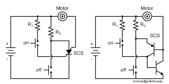
SCS: Motor start/stop circuit, equivalent two‑transistor representation.
Activating the "on" push‑button forward‑biases the base‑emitter junction of the lower transistor via the cathode‑gate to cathode voltage, turning it on. Simultaneously, the upper transistor is primed to conduct because a current path exists from its emitter (the SCS anode) through resistor R2 to the positive supply. As with an SCR, both transistors sustain each other in the on state. The lower transistor then carries the motor’s load current, initiating motor operation. The motor may be stopped by interrupting the supply (natural commutation), but the SCS also offers forced commutation: shorting the anode to the cathode removes emitter current from the upper transistor, halting base current to the lower transistor. When the lower transistor turns off, the upper transistor’s on state is lost, and the motor stops. The SCS remains off until the "on" push‑button is pressed again.
Key Takeaways
- An SCS is essentially an SCR with an additional gate terminal.
- Load current flows through the anode‑gate and cathode terminals; the cathode‑gate and anode provide control.
- Apply a positive cathode‑gate to cathode voltage to turn the SCS on; apply a negative anode‑to‑cathode voltage or short the two to force it off.
- Maintain a positive anode relative to cathode for the device to latch.
[^1] For further reading on forced commutation techniques, refer to the standard semiconductor device textbooks.
Industrial Technology
- Using a Transistor as an Electrically Controlled Switch
- BJT Switching: How Transistors Efficiently Control High‑Current Loads
- Using a Junction Field‑Effect Transistor (JFET) as a Low‑Power On/Off Switch
- Understanding the Shockley Diode: A Comprehensive Guide to PNPN Thyristors
- Silicon‑Controlled Rectifiers (SCRs): Design, Operation, and Practical Applications
- Unijunction Transistor (UJT) & Programmable UJT (PUT): Design, Operation, and Oscillator Applications
- Transistor vs. Resistor: Key Differences Explained
- TIP31C Transistor Pinout & Technical Guide for NPN Power Applications
- Ethernet: The Backbone Powering Industry 4.0 and IoT
- The Critical Role of the Deadman Switch in Robot Safety