


Field‑Effect Controlled Thyristors: MOS‑Gated and MOS‑Controlled Devices
Recent advances in thyristor technology aim to lower the gate trigger current required for conventional silicon‑controlled rectifiers (SCRs). Two notable innovations are the MOS‑Gated Thyristor (MGT) and the MOS‑Controlled Thyristor (MCT).
MOS‑Gated Thyristor (MGT)
The MGT integrates an N‑channel MOSFET at the gate of a standard SCR. The MOSFET’s negligible gate‑drive current (<10 µA) saturates the upper (PNP) transistor, thereby initiating conduction. The overall device therefore requires only a few milliamperes to trigger, a significant improvement over the typical 10–30 mA gate‑current of a bare SCR.
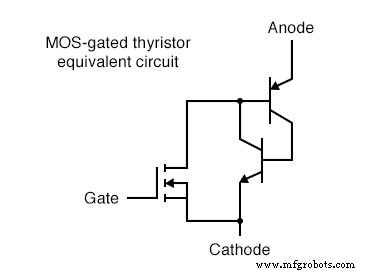
MOS‑Gated Thyristor equivalent circuit
Because the MOSFET is gate‑controlled, the MGT cannot be turned off by a reverse‑triggering pulse. The device will cease conducting only when the gate drive falls below the holding current. Consequently, it offers limited off‑control compared to conventional SCRs.
MOS‑Controlled Thyristor (MCT)
The MCT is a fully controllable thyristor that employs a pair of MOSFETs sharing a common gate terminal. One MOSFET triggers the device, while the other forces it to turn off.
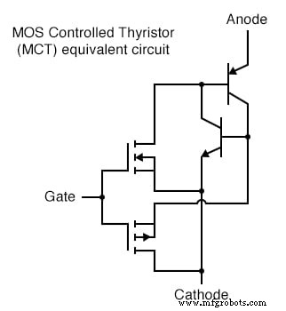
MOS‑Controlled Thyristor (MCT) equivalent circuit
A positive gate voltage (relative to the cathode) turns on the upper N‑channel MOSFET, allowing base current to flow through the upper PNP transistor and latch the pair in the on state. The device remains latched as long as the anode‑cathode current stays above the holding current. When a negative gate voltage (relative to the anode) is applied, the lower MOSFET conducts, shorting the base–emitter of the lower NPN transistor and forcing it into cutoff. This action pulls the upper transistor out of conduction, thereby turning the entire MCT off. With zero gate voltage, neither MOSFET conducts, and the MCT retains its last state—on or off—exhibiting hysteresis.
The MCT can thus be considered a latching IGBT that provides full on/off control via the gate.
Review:- A MOS‑Gated Thyristor uses a single N‑channel MOSFET to trigger a thyristor, delivering extremely low gate‑current requirements.
- A MOS‑Controlled Thyristor (MCT) incorporates two MOSFETs, allowing a positive gate voltage to turn it on and a negative voltage to force it off; zero voltage preserves the previous state.
Industrial Technology
- Designing and Verifying a Basic NAND Gate Circuit with the 4011 IC
- Thyristor Technology: From SCR to TRIAC, GTO, and UJT
- Integrated Circuits: Fundamentals of Digital Logic Gates
- Understanding the NOT Gate (Inverter) in TTL Circuits
- Understanding Multiple-Input Logic Gates: Functions, Truth Tables, and Practical Applications
- CMOS Gate Circuits: Design, Operation, and Comparison to TTL
- Special-Output Logic Gates: Complementary, Tristate, and Bilateral Switches
- Gate Universality: Replicating Any Logic Function with NAND or NOR Gates
- Thyristors: Types, Operation, and the Power of Silicon Controlled Rectifiers (SCRs)
- Hysteresis in Thyristors: How Positive Feedback Enables Latching