


Understanding Multiple-Input Logic Gates: Functions, Truth Tables, and Practical Applications
The Use of Logic Gates
Inverter and buffer circuits cover the entire range of single‑input logic operations. To add real functional depth, we expand the input count, thereby increasing the possible input states and enabling more complex logic behaviour.
With a single input there are only two states: high (1) or low (0). A two‑input gate yields four combinations (00, 01, 10, 11), a three‑input gate yields eight (000, 001, 010, 011, 100, 101, 110, 111), and in general the number of states is 2^n for n inputs:
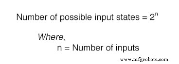
These additional combinations allow a gate’s output to be determined by a specific pattern of 1s and 0s, rather than simply inverting or buffering a single signal.
Below we review each standard multiple‑input gate, providing its symbol, truth table, and a practical LED‑based demonstration. Detailed TTL implementations are covered in later sections.
The AND Gate
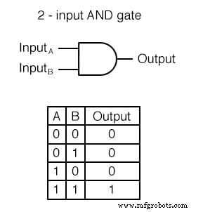
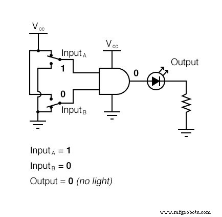
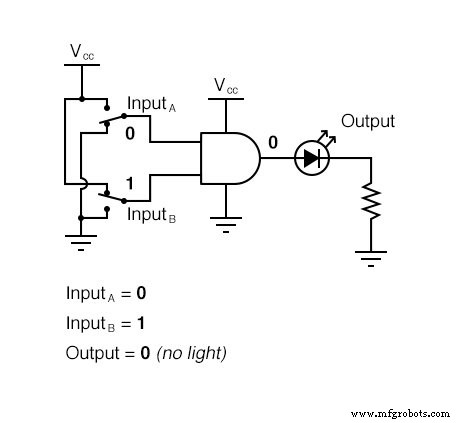
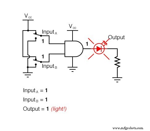
The AND gate outputs a high (1) only when all its inputs are high. Any low input forces the output low.
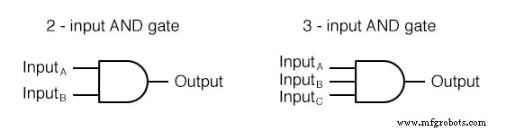
While two‑input AND gates are the most common, the principle extends to any number of inputs.
Truth Table (2‑input)
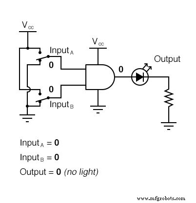
Practical Demonstration
Using an LED to indicate the output, the AND gate lights only when both inputs are high, illustrating the exclusive condition.
The NAND Gate
A NAND gate is simply an AND gate followed by an inverter. Its output is low only when all inputs are high.

Like the AND gate, NAND gates are available with any number of inputs, maintaining the same logical rule.
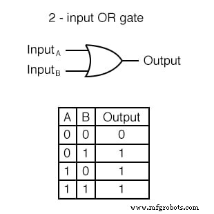
The OR Gate
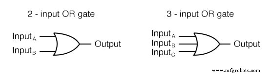
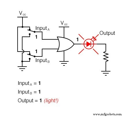
The OR gate outputs high when at least one input is high; it is low only when all inputs are low.
Truth Table (2‑input)
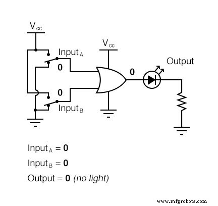
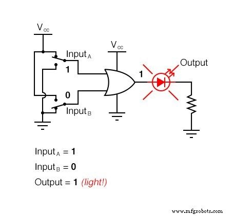
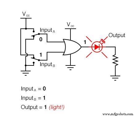
Practical Demonstration
The LED lights for three of the four input combinations, confirming the OR logic.
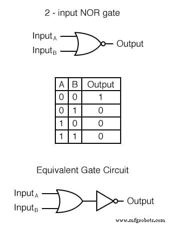
The NOR Gate
A NOR gate is an OR gate followed by an inverter. Its output is high only when all inputs are low.
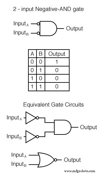
The Negative‑AND Gate
With all inputs inverted before entering an AND gate, the Negative‑AND behaves identically to a NOR gate. Its truth table matches that of the NOR gate.
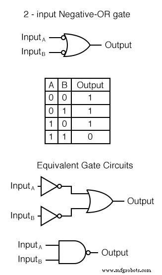
The Negative‑OR Gate
Inverting all inputs to an OR gate produces a NAND‑type behaviour. The truth table is the same as that of a NAND gate.
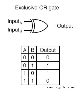
The Exclusive‑OR (XOR) Gate
The XOR gate outputs high when the inputs differ (01 or 10). It is low when the inputs are the same.
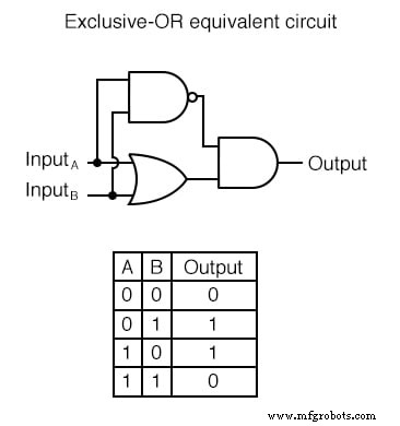
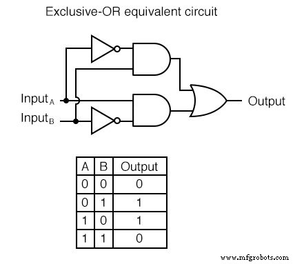
Equivalent Circuits
One construction uses an OR gate, a NAND gate, and an AND gate to suppress the output when both inputs are high.
Another uses two AND gates with inverters, followed by an OR gate to combine the two distinct high conditions.
XOR gates are essential for bit‑by‑bit comparisons, parity checking, and binary‑to‑Gray code conversions.
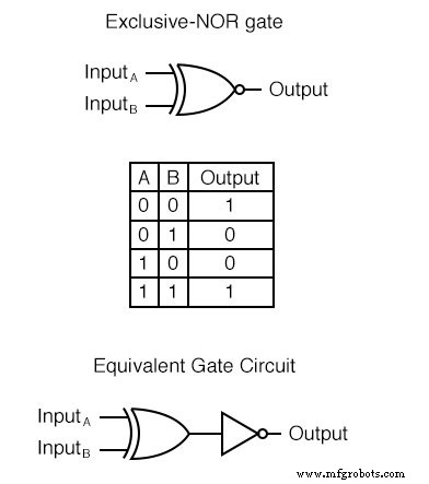
The Exclusive‑NOR (XNOR) Gate
The XNOR gate is simply an XOR gate with its output inverted. It produces a high output when the inputs are identical.
Review
- AND: output high only if all inputs high.
- OR: output high if any input high.
- NAND: output low only if all inputs high.
- NOR: output low if any input high.
- Negative‑AND = NOR.
- Negative‑OR = NAND.
- XOR: output high when inputs differ.
- XNOR: output high when inputs are the same.
Related Worksheets
- Basic Logic Gates Worksheet
- Boolean Algebra Worksheet
Industrial Technology
- Designing and Verifying a Basic NAND Gate Circuit with the 4011 IC
- Building an Enabled NAND‑Gate SR Latch: Parts, Design, and Operation
- Building a NAND‑Based Set‑Reset Flip‑Flop Circuit
- Understanding the Buffer Gate: Amplification and Signal Integrity in Digital Circuits
- Understanding TTL NOR and OR Gates: Circuit Analysis and Conversion
- Special-Output Logic Gates: Complementary, Tristate, and Bilateral Switches
- Gate Universality: Replicating Any Logic Function with NAND or NOR Gates
- Mastering the D Latch: A Clean 1‑Bit Memory Circuit
- Thyristors: Types, Operation, and the Power of Silicon Controlled Rectifiers (SCRs)
- The Definitive Guide to Logic Gate Truth Tables