


Understanding Junction Field-Effect Transistors (JFETs): Gate Current Direction & N‑Channel vs P‑Channel
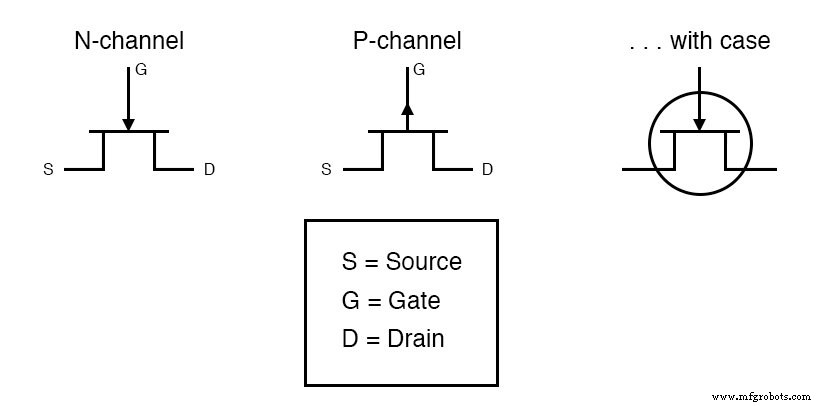
In a junction field‑effect transistor, the arrow on the gate symbol tells you the direction of the gate current when the gate junction is forward‑biased.
- N‑channel JFET: The arrow points into the device, indicating that the gate current flows toward the channel.
- P‑channel JFET: The arrow points away from the device, showing that the gate current exits the channel.
These arrows are crucial for correctly interpreting circuit diagrams and for understanding how the gate controls the channel conductivity.
RELATED WORKSHEETS:
Bipolar Transistors: Symbols, Types, and Applications
Transistors: IGFET (MOSFET) – Depletion & Enhancement Modes Explained
Industrial Technology
- Transistors: IGFET (MOSFET) – Depletion & Enhancement Modes Explained
- CMOS Gate Circuits: Design, Operation, and Comparison to TTL
- Understanding Bipolar Junction Transistors: Structure, Operation, and Amplification
- Junction Field‑Effect Transistors (JFET): Design, Operation, and Advanced Variants
- Insulated‑Gate Field‑Effect Transistors (MOSFETs) – Design, Operation, and Power Variants
- Bipolar Junction Transistors (BJT): Core Principles and Practical Applications
- Understanding Junction Field‑Effect Transistors (JFET): Fundamentals and Applications
- Using a Junction Field‑Effect Transistor (JFET) as a Low‑Power On/Off Switch
- Decoding JFET Quirks: Common Pitfalls & How to Master Them
- Understanding Insulated‑Gate Field‑Effect Transistors (IGFETs)