


Thyristors: Types, Operation, and the Power of Silicon Controlled Rectifiers (SCRs)
Thyristors are a family of bipolar‑conduction semiconductor devices constructed from alternating N‑P‑N‑P layers. The family includes silicon controlled rectifiers (SCRs), TRIACs, gate turn‑off switches (GTOs), silicon controlled switches (SCSs), AC diodes (DIACs), unijunction transistors (UJT), and programmable unijunction transistors (PUT). This article focuses on the SCR while briefly noting the GTO.
In 1950, Shockley proposed the four‑layer diode thyristor. General Electric later realized the design, and SCRs have since evolved to handle power levels from a few watts to several megawatts. The smallest units—packaged like small‑signal transistors—switch a few hundred milliamps at about 100 VAC. The largest commercial devices measure 172 mm in diameter and can handle 5,600 A at 10,000 V. High‑power SCRs may be fabricated on wafers several inches across.
Silicon Controlled Rectifier (SCR)
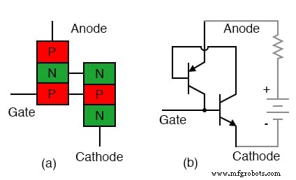
The SCR is a four‑layer diode that incorporates a gate terminal. When a positive gate pulse is applied, the internal NPN‑PNP transistor pair is triggered into conduction. Positive feedback between the two transistors sustains the on state even after the gate pulse is removed. The device continues to conduct as long as the anode remains positively biased. In DC, conduction is permanent; in AC or pulsating DC, it stops when the anode voltage falls to zero—this is the commutation point.
The doping structure is illustrated in the figure below: the cathode (N⁺) and anode (P⁺) are heavily doped, while the middle N⁻ and P layers are lightly doped, forming the transistor bases. In high‑power SCRs, this structure can span an entire wafer.
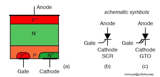
SCR and GTO symbols are shown in the diagram: the basic diode symbol indicates unidirectional conduction, while the gate lead marks control capability. The GTO symbol features bidirectional arrows, signifying that a negative gate pulse can turn the device off.
Beyond silicon, silicon carbide (SiC) SCRs are under development. SiC offers superior thermal conductivity—second only to diamond—allowing either smaller form factors or higher power handling at elevated temperatures.
Key Takeaways
- SCRs are the most common four‑layer thyristor.
- A positive gate pulse triggers conduction, which persists until the anode voltage drops to zero.
- SCRs excel in AC or pulsating DC applications where continuous conduction is required.
- The GTO can be shut down with a negative gate pulse.
- SCRs can manage up to 5.6 kA and 10 kV, translating to megawatt‑level power.
Related Resources
Industrial Technology
- Designing and Verifying a Basic NAND Gate Circuit with the 4011 IC
- Integrated Circuits: Fundamentals of Digital Logic Gates
- Understanding the NOT Gate (Inverter) in TTL Circuits
- Understanding Multiple-Input Logic Gates: Functions, Truth Tables, and Practical Applications
- CMOS Gate Circuits: Design, Operation, and Comparison to TTL
- Special-Output Logic Gates: Complementary, Tristate, and Bilateral Switches
- Gate Universality: Replicating Any Logic Function with NAND or NOR Gates
- Hysteresis in Thyristors: How Positive Feedback Enables Latching
- Silicon‑Controlled Rectifiers (SCRs): Design, Operation, and Practical Applications
- Field‑Effect Controlled Thyristors: MOS‑Gated and MOS‑Controlled Devices