


Silicon‑Controlled Rectifiers (SCRs): Design, Operation, and Practical Applications
Shockley Diodes and Silicon Controlled Rectifiers (SCRs)
Shockley diodes, while limited in scope, can be transformed into powerful amplifying devices—called silicon‑controlled rectifiers (SCRs)—by adding a single latch mechanism. This third terminal, the gate, enables the device to latch into conduction with minimal gate drive, effectively turning a passive diode into an active switch.
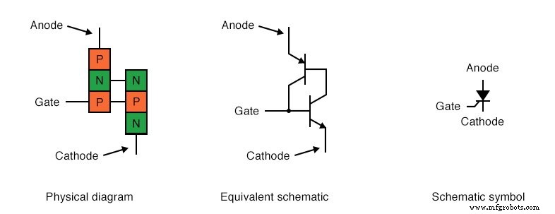
The transition from a Shockley diode to an SCR is achieved by attaching an additional wire to the existing PNPN structure, creating the classic four‑terminal thyristor shown below.
The Silicon‑Controlled Rectifier (SCR)
SCR Conduction
When the gate is left floating, an SCR behaves identically to a Shockley diode, relying on breakover voltage or a rapid voltage rise between anode and cathode to latch. However, by applying a modest voltage between gate and cathode, the lower transistor’s base is driven on, causing the upper transistor to conduct. The resulting base current from the upper transistor sustains the lower transistor, eliminating the need for continued gate drive. Because the gate current is orders of magnitude smaller than the anode‑cathode current, the SCR demonstrates true amplification.
Triggering/Firing
In practice, the most common way to latch an SCR is by intentional gate firing. Manufacturers select devices with breakover voltages well above the maximum supply voltage so that the SCR can only be turned on by a deliberate gate pulse. This ensures reliable operation in power‑control applications.
Reverse Triggering
SCRs can be shut off by shorting gate to cathode or by reverse‑triggering the gate with a negative voltage. However, this method requires substantial gate current because it must divert the entire collector current of the upper transistor. Gate‑Turn‑Off thyristors (GTOs) are engineered for easier off‑switching, but even they often demand gate currents up to 20 % of the anode current. The GTO symbol is illustrated below.
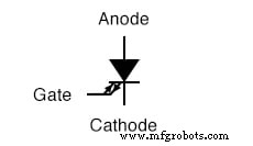
The Gate Turn-Off thyristor (GTO)
SCRs vs GTOs
Both devices share the same two‑transistor topology, but GTOs feature an NPN transistor with a higher β, enabling a smaller gate current to control the device. This enhanced control is why GTOs are sometimes called Gate‑Controlled Switches (GCS).
Testing SCR Functionality with an Ohmmeter
A quick way to identify SCR terminals is to use an ohmmeter. Because the gate‑cathode path contains a single PN junction, the meter should show continuity when the red lead is on the gate and the black lead on the cathode, as depicted:
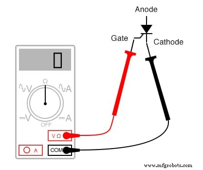
Rudimentary test of SCR
All other terminal pairs will read open. Note that this test is only a rough check; a defective SCR can still show proper continuity. Comprehensive testing requires loading the device and measuring its current‑voltage characteristics.
On multimeters with a diode‑check function, the gate‑cathode voltage may be lower than the typical 0.7 V for a silicon junction if an internal gate‑cathode resistor is present. This resistor, common in larger SCRs, protects against accidental triggering from noise or static discharge. It also causes the meter to show continuity in both directions between gate and cathode.
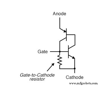
Larger SCRs have gate to cathode resistor.
Sensitive Gate SCRs
SCRs without the internal resistor are termed sensitive‑gate devices because a small positive gate pulse can latch them. A practical diagnostic circuit for such SCRs is shown below, using a DC supply and two push‑buttons: one to fire and one to release the gate.
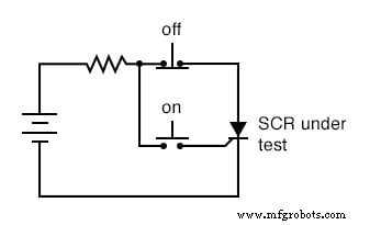
SCR testing circuit
Pressing the “on” button connects the gate to the anode, allowing a brief gate current to trigger the SCR. Once latched, the load remains powered even after the button is released. The “off” button breaks the gate connection, forcing the SCR into dropout and turning the load off.
Holding Current
If the SCR fails to latch, the issue may lie in the load. Each SCR has a minimum holding current—typically between 1 mA and 50 mA for larger units—required to maintain conduction after gate drive stops. Datasheets from manufacturers such as ABB, Siemens, or ON‑Semiconductor provide exact holding current values for specific part numbers.
A more comprehensive test includes measuring the forward breakover voltage by raising the DC supply until the SCR latches on its own, or using a pulse generator to assess the critical voltage‑rise rate. Note that many power SCRs have breakover ratings of 600 V or more.
Beyond diagnostics, this simple test circuit can serve as a start/stop control for DC loads like motors or lamps, as illustrated:
DC motor start/stop control circuit
The “Crowbar” Circuit
A crowbar circuit uses an SCR in parallel with a DC power supply to create a controlled short circuit in case of overvoltage. A fuse or series resistor limits the fault current, protecting the supply and the SCR. The gate is driven by a voltage‑sensing circuit that triggers the SCR when the output voltage exceeds a preset threshold.
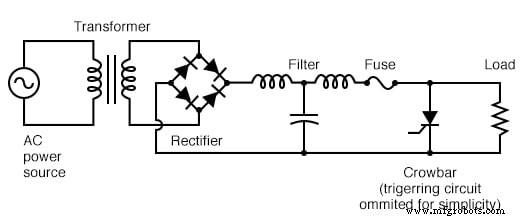
Crowbar circuit used in DC power supply
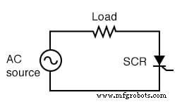
SCRs in AC Power Control
Although SCRs are inherently DC devices, they are widely used for AC power control. In an AC circuit, the device conducts only during the positive half‑cycle when the anode is more positive than the cathode. At the zero‑crossing, natural commutation turns the SCR off, allowing it to be fired again on the next half‑cycle. This results in a chopped sine wave whose duty cycle can be adjusted by controlling the gate firing angle.
The DIAC, a bidirectional hysteresis device, demonstrates this principle: once its breakover voltage is exceeded, it conducts until the current falls to zero. In contrast, an SCR’s firing angle can be precisely set by the gate drive.
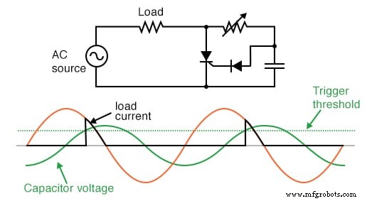
DIAC bidirectional response
For full‑wave control, two SCRs are typically wired in antiparallel or in a bridge configuration. Pulse transformers or isolated gate drivers are used to supply the gate pulses when the SCR cathodes are not common.
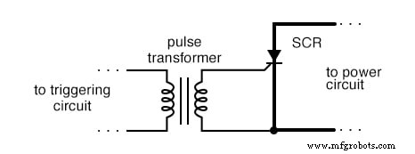
Transformer coupling of trigger signal provides isolation.
Controlled bridge rectifiers can be single‑ or three‑phase. In a three‑phase design, each phase uses two SCRs in a bridge, allowing precise power control across all phases.
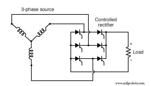
Three‑phase bridge SCR control of load
Key Takeaways
- Adding a gate terminal turns a Shockley diode into an SCR, providing latch‑based switching.
- Gate firing uses a tiny current to latch the device; breakover and voltage‑rise triggering are alternatives but less reliable.
- Reverse firing can turn off an SCR, but it requires large gate currents; GTOs simplify this process.
- Ohmmeter tests identify gate‑cathode continuity but must be followed by load testing.
- Holding current is critical; consult datasheets for specific values.
- SCRs are the core of AC power control and crowbar protection circuits.
- Proper gate drivers and isolation transformers are essential for multi‑SCR systems.
Related Resources
Industrial Technology
- Half‑Wave Rectifier Experiment: Build, Measure, and Simulate a Simple AC‑to‑DC Motor Circuit
- Understanding the NOT Gate (Inverter) in TTL Circuits
- Understanding the Buffer Gate: Amplification and Signal Integrity in Digital Circuits
- Demystifying the XOR Gate: The Exclusive‑OR Function in Digital Logic
- Thyristors: Types, Operation, and the Power of Silicon Controlled Rectifiers (SCRs)
- Silicon‑Controlled Rectifiers (SCRs): Design, Operation, and Practical Applications
- Silicon‑Controlled Switch (SCS): Design, Operation, and Forced Commutation
- Mastering Gate Driver Power Architecture for EV Half‑Bridge Converters
- Master Silicon Controlled Rectifiers (SCR) – A Complete Guide
- Rectifier Circuits: Fundamentals, Operation, and Design Guidelines