


Constructing a Reliable Low‑Voltage AC/DC Power Supply: Bridge Rectifier & Capacitive Filter
PARTS AND MATERIALS
- Low‑voltage AC power supply (6 V RMS, 120 VAC input)
- Bridge rectifier pack (e.g., Radio Shack #276‑1185 or equivalent)
- Electrolytic capacitor, 1000 µF, ≥25 V DC (Radio Shack #272‑1047 or equivalent)
- Four “banana” jack binding posts or similar terminal hardware (Radio Shack #274‑662 or equivalent)
- Metal enclosure (preferably a box that can act as a heat sink)
- 12‑V, 25‑W incandescent bulb (suitable for heavy‑load testing)
- Lamp socket compatible with the bulb
NOTES FOR PARTS AND MATERIALS
Using a commercial bridge rectifier pack is preferable to assembling four discrete diodes because the pack is designed for a mounted heat sink and offers reliable, maintainable connections. A metal enclosure serves as an effective heat sink for the rectifier, helping keep the semiconductor junction temperature within safe limits.
The electrolytic capacitor’s working voltage should be at least twice the RMS AC voltage from the power supply to accommodate peak voltage and provide a safety margin. For a 6 V RMS supply, a 25 V capacitor is adequate; a higher voltage rating is fine if the size and cost are acceptable.
High‑wattage 12‑V lamps (25 W or 50 W) are readily available from RV and boating supply outlets. They provide a realistic heavy load for evaluating ripple reduction.
CROSS‑REFERENCES
Lessons In Electric Circuits, Volume 2, Chapter 8: Filters
LEARNING OBJECTIVES
- Understand how a capacitive filter smooths the DC output of a rectifier.
- Recognize the importance of heat sinking for power semiconductors.
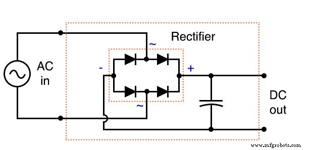
SCHEMATIC DIAGRAM
ILLUSTRATION
INSTRUCTIONS
In this experiment you will build a rectifier and filter circuit that converts the low‑voltage AC output of your earlier power‑supply module into a stable DC source. The resulting supply can replace a battery in battery‑powered experiments and can be expanded into a self‑contained 120 VAC → DC unit by adding a transformer, cord, and plug to the AC side.
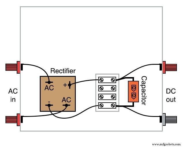
CONSTRUCTING THE RECTIFIER PART
The bridge rectifier must handle at least the transformer's secondary current rating and have a voltage rating of ≥2× the RMS secondary voltage to allow for peak voltage and safety margin. The Radio Shack pack (25 A, 50 V) comfortably meets these requirements for a 6 V AC supply.
Most rectifier packs include quick‑disconnect terminals. Use crimped “quick‑disconnect” lugs on the wire ends for a reliable, replaceable connection. Avoid soldering directly onto semiconductor pins to prevent heat damage and to maintain easy maintenance.
Secure the rectifier inside the metal enclosure. The enclosure’s surface area functions as a heat sink, dissipating heat generated by high current flow.
CONSTRUCTING THE FILTER PART
Connect the electrolytic capacitor across the rectifier’s DC output terminals, ensuring correct polarity. The capacitor acts as a low‑impedance reservoir that smooths the DC waveform, reducing ripple voltage. Because electrolytic capacitors are polarity sensitive, a reversed connection can cause catastrophic failure—use a test point or multimeter to verify polarity before final assembly.
TESTING THE CIRCUIT
After assembly, connect the rectifier/filter unit to the low‑voltage AC supply as shown:
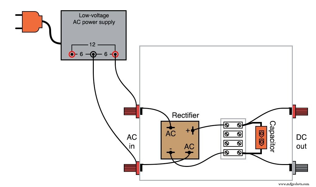
Measure the AC output of the power supply; it should be approximately 6 V RMS. Then switch your multimeter to DC mode and measure the rectifier output. The DC voltage will be close to the peak AC voltage (≈8.5 V), illustrating the filtering effect.
To assess ripple, set your meter to AC volts (or AC millivolts). The ripple will be substantially lower than in an unfiltered rectifier. For a qualitative check, you can “listen” with an audio detector: a faint tone indicates residual ripple.
Next, connect the 25‑W bulb across the DC output:
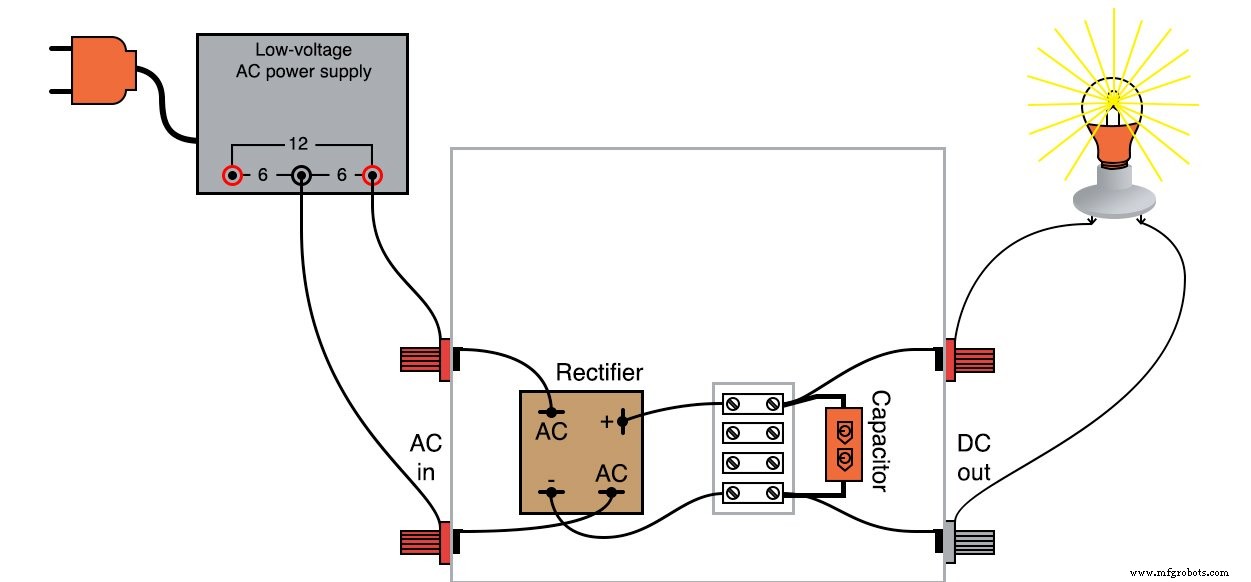
Re‑measure the ripple. With the heavy load, the filter capacitor discharges between peaks, so ripple increases. This demonstrates the load‑dependent nature of filtering.
REDUCING RIPPLE
If lower ripple is required under load, increase the filter capacitance or implement a multi‑stage filter such as a capacitor‑inductor‑capacitor (C‑L‑C) network. For example:
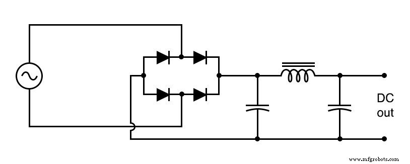
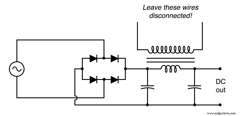
Use an iron‑core choke with adequate current rating; its inductance blocks AC ripple while passing DC. If a suitable choke is unavailable, the secondary winding of a step‑down transformer can serve as a choke—leaving the primary open—because the transformer's magnetic core naturally provides inductive impedance to ripple.
COMPUTER SIMULATION
To validate your design, run a SPICE simulation using the following netlist:
Fullwave bridge rectifier v1 1 0 sin(0 8.485 60 0 0) rload 2 3 10k c1 2 3 1000u ic=0 d1 3 1 mod1 d2 1 2 mod1 d3 3 0 mod1 d4 0 2 mod1 .model mod1 d .tran .5m 25m .plot tran v(1,0) v(2,3) .end
Adjust the load resistor to explore ripple behavior under different loading conditions.
RELATED WORKSHEET
- Basic AC‑DC Power Supplies Worksheet
Industrial Technology
- Mastering AC Circuit Equations: Impedance, Reactance & Resonance
- Power Sources: AC and DC Explained
- Rectifier Circuits: From Half‑Wave to Polyphase Full‑Wave Designs
- Ensuring Electrical Safety: Grounding, Polarized Plugs, GFCIs, and AFCIs
- Understanding Single‑Phase Power Systems: Efficiency, Safety, and Design
- Calculating Power Factor in AC Circuits: Theory, Impact, and Practical Correction
- Dual ±12 VDC Power Supply from 230 VAC – Circuit Diagram & Guide
- Reliable Emergency Light Circuit: Expert Step‑by‑Step Guide
- Wireless Power Transfer: Fundamentals and Benefits
- Designing a Compact Flyback Power Module for RFID Readers