


Current Divider Circuits: Theory, Formula, and Practical Applications
A parallel network is often called a current divider because it splits the total supply current into predictable fractions that depend only on the branch resistances. This behavior is a direct consequence of Ohm’s law and the fact that all parallel elements share the same voltage.
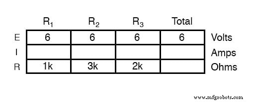
To illustrate, consider the following simple parallel circuit powered by a 6‑V source. The resistors are labelled R1, R2, and R3 with values that produce branch currents of 6 mA, 2 mA, and 3 mA, respectively.
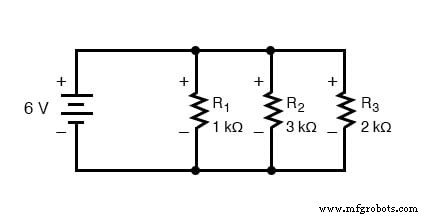
Because the voltage across every branch is 6 V, the current through each resistor follows directly from Ohm’s law: I = V / R. Filling in the table yields the branch currents shown above.
Adding the branch currents gives the total current supplied by the source:
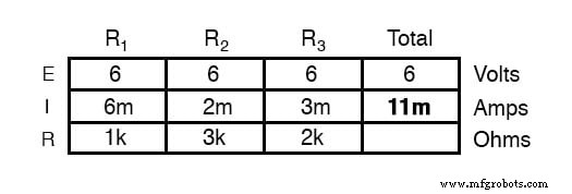
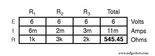
Using Ohm’s law again, the total resistance of the network is calculated as RTotal = V / ITotal = 6 V / 11 mA ≈ 545 Ω. Alternatively, applying the parallel‑resistance formula to the individual resistances yields the same result.
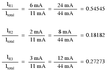
Notice how the current through each resistor is inversely proportional to its resistance. For instance, R1 carries twice the current of R3 because it has half the resistance.
Changing the supply voltage scales all branch currents proportionally, but the ratios between them remain unchanged. Even if the source voltage quadruples, the fraction of the total current flowing through each branch is constant.
Deriving the Current Divider Formula
By rearranging Ohm’s law for a single branch and recognizing that the voltage across each branch is identical, we obtain the compact expression:
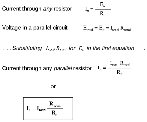
This equation states that the current through resistor Rn equals the total current multiplied by the ratio of the network’s total resistance to that resistor’s value. It is a quick way to compute any branch current when the total current and resistances are known.
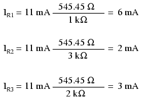
Example Using the Formula
Re‑examining the original circuit, we can compute the branch currents directly from the total current (11 mA) and total resistance (≈545 Ω) without solving each branch individually:
Comparing this to the voltage divider equation clarifies the difference: in a voltage divider, the ratio is Rn / RTotal; in a current divider, the ratio is RTotal / Rn. Remember, both ratios must be less than one because each represents a fraction of the total.
When to Use the Current Divider Formula
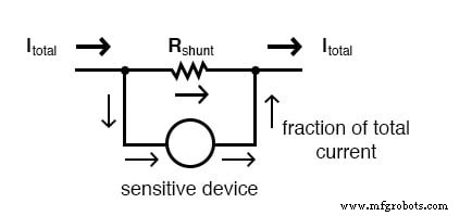
Current divider circuits are essential in measurement systems where only a fraction of the load current can be safely routed to a sensitive detector. For example, in an electric‑meter circuit a shunt resistor is sized using the current divider formula so that a precise percentage of the line current reaches the meter’s sensing element.
Key Takeaways
- Parallel networks divide the total current among branches according to their resistances:
In = ITotal · (RTotal / Rn). - The current ratio between any branch and the total current is independent of the source voltage.
- In a current divider, the total resistance is always less than any individual branch resistance, so the ratio in the formula is
RTotal / Rn. - Electric meters and other measurement devices use this principle to create accurate, scaled currents for sensors.
Further Learning
Industrial Technology
- Hands‑On Guide to Current Dividers: Build, Measure, and Simulate with a 6 V Battery
- The Quadratic Formula: A Reliable Tool for Solving Second‑Degree Equations
- DIAC: The Bidirectional Trigger for AC Thyristors
- Voltage Divider Circuits: Mastering Series Resistor Analysis & Potentiometers
- Analyzing a Parallel R‑L‑C Circuit: Impedance, Current, and SPICE Simulation
- Analyzing Series-Parallel RC and RL Circuits with Complex Impedance
- Electrical Signal Propagation at Light Speed: A 186,000‑Mile Thought Experiment
- Master Voltage Divider Rule (VDR): Step‑by‑Step Examples for Resistor, Inductor, and Capacitor Circuits
- Master the Current Divider Rule: Expert Solutions for AC & DC Parallel Circuits
- Mastering Parallel Transistors: A Comprehensive Guide to Safe and Efficient Circuit Design