


Passive Averager and Op‑Amp Summer Circuits: From Averaging to Addition
When three identical resistors share a common node, each fed with a separate voltage source, the voltage at that node is the arithmetic mean of the three inputs. This simple arrangement is the classic passive averager and is a direct application of Millman’s Theorem, which predicts the node voltage for multiple sources connected through individual resistances.
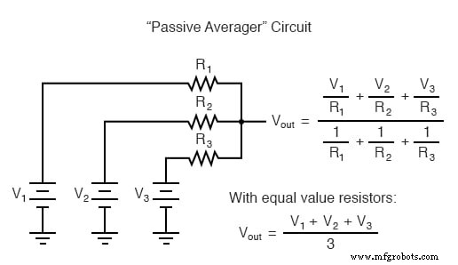
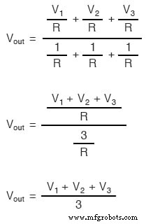
Because the resistors are equal, Millman’s expression collapses to the straightforward average:
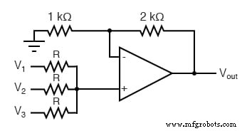
Integrating this averager with a non‑inverting op‑amp that has a gain of 3 transforms the averaging operation into a true addition. The op‑amp’s feedback network (a 2 kΩ/1 kΩ divider) sets the gain, while the averaged input is multiplied by that gain to produce an output equal to the sum of the three source voltages.
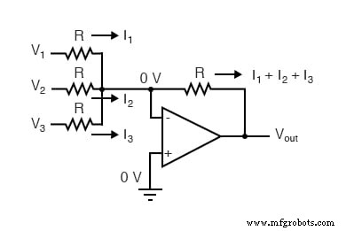
With an inverting configuration, the same passive averager becomes part of the feedback loop. The op‑amp’s virtual ground pins all input currents to zero volts, but the currents through the equal resistors still add algebraically. The resulting output is the negative of the input sum, delivering an inverting summer.
These summer (adder) circuits are fundamental in analog computing, enabling precise signal summation with minimal component count thanks to the op‑amp’s high differential gain.
Review:
- A summer adds multiple analog voltages. The two primary op‑amp implementations are non‑inverting and inverting.
Related Worksheet:
- Summer and Subtractor Op‑Amp Circuits Worksheet
Industrial Technology
- Sensitive Voltage Detector: Build a High‑Sensitivity Audio Signal Detector
- Understanding Differentiator and Integrator Op‑Amp Circuits
- Power Supply Circuits: Types, Design Principles, and Performance
- Understanding Power in Electric Circuits: Measurement & Significance
- Voltage Divider Circuits: Mastering Series Resistor Analysis & Potentiometers
- Understanding AC Inductor Circuits: Reactance, Phase Shift, and Power Dynamics
- AC Capacitor Circuits: Capacitive Reactance, Phase Shift, and Power Behavior
- Master Voltage Divider Rule (VDR): Step‑by‑Step Examples for Resistor, Inductor, and Capacitor Circuits
- Schmitt Trigger Explained: Design, Function, and Practical Applications
- Voltage Doubler: A Lightweight, Cost‑Effective Alternative to Transformer‑Rectifier Circuits