


Essential Transistor Ratings and Package Types for Bipolar Junction Transistors
Transistors, like all semiconductor devices, have finite voltage and current limits beyond which they fail. Because of their complex internal structure, BJTs exhibit a broader set of rating parameters than simpler components. The following sections detail the most common specifications you’ll encounter.
Power Dissipation
When a transistor conducts between collector and emitter, it drops voltage across those terminals. The instantaneous power loss is simply the product of collector current (IC) and collector‑emitter voltage (VCE). Manufacturers provide a maximum continuous wattage that the device can safely dissipate without overheating.
Thermal considerations are paramount: bipolar transistors are more vulnerable to heat than many other semiconductors. Power ratings are always referenced to an ambient temperature of 25 °C. In environments hotter than this, the allowable power must be derated to prevent premature failure.
Reverse Voltages
Like diodes, BJTs have maximum reverse‑bias limits for each of their PN junctions. These include emitter‑base (VEB), collector‑base (VCB), and collector‑emitter (VCE) voltages. Typical small‑signal transistors can tolerate around 7 V across the emitter‑base junction; exceeding this can damage the device. The collector‑emitter rating, critical for switching applications, usually ranges from 60–80 V for small‑signal parts and can reach 1 kV in high‑power devices such as CRT deflection tubes.
Collector Current
The datasheet lists a maximum collector current (IC,max). Small‑signal BJTs typically support tens to hundreds of milliamps, whereas power transistors handle tens of amperes. The maximum value assumes the transistor is saturated (VCE ≈ 0 V). If the transistor operates outside saturation, the power dissipation may exceed the rated value before the current limit is reached.
Saturation Voltages
In saturation, a BJT behaves like a low‑resistance switch. Manufacturers quote a maximum VCE(sat) for a given base drive. Values near 0.3 V are common for low‑power parts; higher drive currents can reduce this further. The base‑emitter forward drop (VBE) is typically ≈0.7 V, similar to a silicon diode.
Beta (hFE)
Beta is the ratio of collector to base current and defines a transistor’s current amplification. It is not a fixed number; manufacturers provide minimum, typical, and maximum values across a range of operating conditions. For example, the 2N3903 can have β from 15 to 150 depending on IC. Beta peaks at medium currents and falls at both low and high extremes.
Alpha (α)
Alpha, the ratio of collector to emitter current, is related to beta by α = β/(β + 1). While less commonly cited, it is useful for high‑frequency and precision analyses.
Package Types
The physical package determines a transistor’s thermal performance. Smaller plastic packages such as TO‑92 can dissipate a few hundred milliwatts, whereas metal canisters like TO‑18 and TO‑39 handle several hundred milliwatts. Plastic power packages—TO‑220 and TO‑247—are rated for over 100 W, approaching the capability of all‑metal TO‑3 cases. These packages feature a heat‑conductive metal slug that attaches to a heatsink; a thin thermally conductive grease improves heat transfer. Without a heatsink, a TO‑220 can safely dissipate only about 1 W in free air. Datasheet ratings presume proper heatsinking and apply a derating curve versus case temperature.
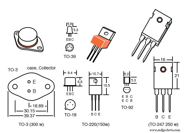
Transistor packages come in many standardized sizes. Pin‑out can vary even within the same package family, so always consult the part number or perform electrical tests to confirm the device.
Quick Review
- Power dissipation – maximum sustained wattage.
- Reverse voltages – VCE, VCB, VEB limits.
- Collector current – IC,max.
- Saturation voltage – VCE(sat) in a fully conducting state.
- Beta – β = IC/IB.
- Alpha – α = IC/IE = β/(β + 1).
- Package – larger packages enable higher power dissipation.
Related Worksheets
- Bipolar Junction Transistor (BJT) Theory Worksheet
Industrial Technology
- Essential DC Circuit Equations and Laws for Engineers
- How to Identify and Test a Bipolar Junction Transistor (BJT) with a Multimeter
- BJT Biasing Techniques: Mastering Class A, B, AB, C, and D Amplifiers
- JFET Transistor Ratings & Package Overview – Choosing the Right Device
- Choosing the Right Transistor Ratings and Packages for IGFETs
- Passive Averager and Op‑Amp Summer Circuits: From Averaging to Addition
- Understanding Voltage and Current: The Foundations of Electrical Flow
- Capacitors & Calculus: How Voltage Change Drives Current
- Advanced Analysis of DC Reactive Circuits with Non‑Zero Initial Conditions
- Three‑Phase Y and Delta Configurations: Design, Analysis, and Reliability