


Understanding Current Mirrors in Bipolar Junction Transistor Circuits
Bipolar Junction Transistor or BJT Current Mirror
A current mirror is one of the most widely used BJT circuits. It acts as a simple, reliable current regulator, maintaining a nearly constant current through a load over a broad range of load resistances.
In active mode, the collector current (IC) equals the base current (IB) multiplied by the transistor’s current gain, β. The ratio of collector to emitter current is α, which can be derived from β as α = β/(β+1). This relationship shows that, just as a fixed base current fixes IC, a fixed emitter current will fix IC when the transistor remains in its active region.
The base‑emitter junction of a BJT behaves like a PN diode. The well‑known diode equation predicts the junction current for a given forward voltage and temperature:
Diode Equation Formula
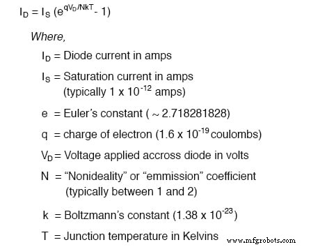
If the forward voltage and temperature are held constant, the PN junction current is constant. Consequently, maintaining a constant base‑emitter voltage (VBE) forces the emitter current (IE) and therefore the collector current (IC) to remain constant, provided the transistor has sufficient VCE to stay in active mode.
To hold VBE steady, a forward‑biased diode is placed in parallel with the base‑emitter junction, as shown:
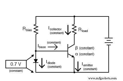
The diode establishes an approximate 0.7‑V drop, keeping the base voltage—and thus the base, emitter, and collector currents—steady. The actual voltage will vary slightly with current and temperature, but both the diode and the transistor’s base‑emitter junction share the same PN junction physics, so the emitter current tracks the diode current closely. Adjusting the bias resistor (Rbias) changes the diode current, which directly sets the emitter and collector currents.
Because α for a typical BJT is close to unity, the collector current essentially mirrors the diode current. The load current through Rload is therefore set by the bias resistor, making the current mirror a convenient way to regulate load current with a single resistor.
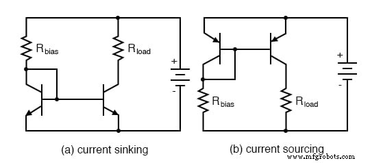
For tighter matching of the two PN junctions, a second transistor can replace the diode, yielding a pair of matched transistors in a current‑mirror configuration:
Temperature matching is critical because the diode equation is temperature dependent. Discrete components can be glued back‑to‑back, while integrated circuits typically place the matched transistors close together to ensure equal heating.
The topology shown with two NPN transistors (Fig. a) is a current‑sinking mirror: the regulating transistor draws current from the load to ground. If a grounded load is required, a current‑sourcing mirror using PNP transistors (Fig. b) can be employed.
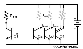
In IC design, resistors are often replaced by transistor‑based current sources. A single voltage reference can drive multiple current mirrors: Q2, Q3, and Q4 share the same reference current, and their load currents scale with transistor area. For example, a transistor with twice the area will provide twice the current, eliminating the need for parallel resistors.
Current mirrors are frequently used as load devices in integrated amplifiers. In the 741 op‑amp, for instance, Q13’s mirror replaces the resistive load of Q15 and Q17, demonstrating how mirrors replace resistors in high‑density ICs.
REVIEW:
- A current mirror is a transistor circuit that fixes the load current via a simple bias resistor.
- Precise operation requires the transistors to share the same temperature; discrete parts can be glued together, while ICs place them in close proximity.
- Current mirrors come in two basic configurations: current‑sinking (NPN) and current‑sourcing (PNP).
RELATED WORKSHEETS:
- Active Loads in Amplifier Circuits Worksheet
- Differential Transistor Amplifiers Worksheet
Industrial Technology
- Hands‑On Guide to Current Dividers: Build, Measure, and Simulate with a 6 V Battery
- Build a Reliable Current Mirror Circuit: Step‑by‑Step Guide
- Mastering Time Constant Calculations for RC and RL Circuits
- Understanding the Derivative of a Constant: Why It Is Zero
- Common-Emitter Amplifier Limitations: Distortion, Temperature, and High‑Frequency Challenges
- Insulated‑Gate Bipolar Transistors (IGBTs): Merging FET Precision with BJT Power
- DIAC: The Bidirectional Trigger for AC Thyristors
- Understanding Electrical Resistance and Circuit Safety
- Understanding Meter Design: From Classic Galvanometers to Modern Digital Displays
- Current Signal Systems: The 4‑20 mA Loop Explained