


Single‑Ended vs. Differential Amplifiers: Design, Operation, and Applications
Single‑Ended vs. Differential Amplifiers
In circuit design, the complex internals of an amplifier are often collapsed into a single triangle symbol. This abstraction keeps schematics readable while still conveying the essential function of the device.
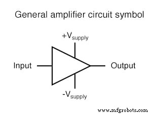
The symbol shows two power‑supply pins (+V and –V) and single input and output leads. Because all signal nodes are referenced to a common point called ground, the input and output are depicted as single conductors. In many practical circuits, one supply rail is tied to ground.
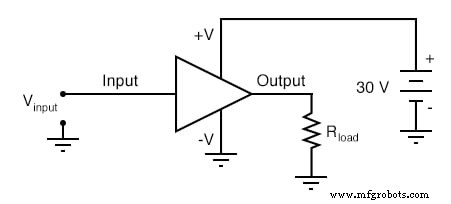
A realistic amplifier circuit, complete with input source, load resistor, and power supply, looks like this:
How the Amplifier Works
The schematic tells you at a glance: an input voltage V_in is amplified and drives a load R_load. To perform any detailed analysis, you would add the voltage gain A_V, current gain A_I, power gain A_P, and the bias or Q‑point.
When an amplifier must deliver a true AC waveform—i.e., swing both positive and negative—a split (or dual) power supply is used. Ground is positioned midway between the positive and negative rails, giving the amplifier a symmetric voltage reference.
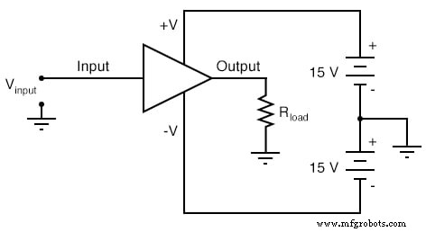
With a 30 V total supply, a split supply produces ±15 V rails, allowing the output to swing from +15 V to –15 V. The peak‑to‑peak amplitude remains unchanged, but the output can now cross zero without additional coupling components.
Differential Amplifiers
Unlike single‑ended amplifiers, a differential amplifier amplifies the voltage difference between two inputs. Using the triangle symbol, its schematic is:
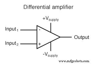
The two input pins are labeled (–) and (+), reflecting the opposite influence each has on the output. The output pin is on the right side, and the power rails are on top and bottom.
For a differential amplifier with a voltage gain of 4, the input‑output relationships are shown in the table below:
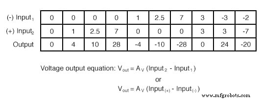
Key takeaways:
- An increasing voltage on the (+) input drives the output upward.
- An increasing voltage on the (–) input drives the output downward.
- The (–) pin is the inverting input; the (+) pin is the non‑inverting input.
To aid understanding, engineers often model a differential amplifier as a variable voltage source controlled by a sensitive voltmeter:
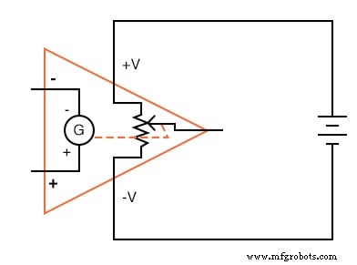
In this abstraction, the galvanometer (a sensitive voltmeter) sets the output voltage, while the input signals only influence the setting. The actual output current is drawn from the power supply, not from the input signals.
Polarity Rules
When the differential voltage matches the labeling of the inputs, the output is positive. When the polarity conflicts, the output is negative. This mirrors how a digital voltmeter displays voltage: the red lead is considered positive.
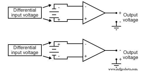
Because a differential amplifier amplifies only the difference between its two inputs, the output polarity depends solely on the relative signs of those inputs, not on any single input relative to ground.
Practical Applications
Differential amplifiers are ubiquitous in instrumentation and control systems:
- In analog computers, they compare two mathematical signals.
- In process instrumentation, they measure differences between physical quantities (e.g., fluid levels in two tanks) and can trigger alarms when the difference exceeds a threshold.
- In feedback loops, they compare a process variable with a setpoint. The resulting differential signal drives a controller (valve, motor, etc.) to keep the process near the setpoint.
Quick Review
- A triangle symbol is a shorthand for an amplifier; the wide side is the input, the narrow side is the output.
- A split or dual power supply provides both +V and –V rails with ground at the midpoint, enabling true AC output.
- Most amplifiers have a single input and a single output; differential amplifiers have two inputs and one output, with the output proportional to the input difference.
- The output voltage of a differential amplifier is given by
V_out = A_V (V_noninv – V_inv).
Related Worksheet
- Basic Operational Amplifiers Worksheet
Industrial Technology
- Common‑Emitter Amplifier: Design, Measurement, and Feedback Techniques
- Designing a High‑Gain Multi‑Stage Common‑Emitter Amplifier with Negative Feedback
- Designing a High‑Gain Differential Amplifier with NPN Transistors
- Non‑Inverting Amplifier: Build, Test, and Master Op‑Amp Gain Control
- Essential DC Circuit Equations and Laws for Engineers
- Understanding Amplifier Gain: Voltage, Current, and Power
- Common‑Collector Amplifier: Emitter‑Follower Fundamentals & Applications
- Designing a Practical Differential Amplifier with Controlled Gain
- Master Class C Amplifiers: Comprehensive Guide & Expert Insights
- Understanding Voltage Amplifiers: How They Boost Signal Voltage