


Calculating Voltage and Current in Reactive DC Circuits
You can precisely determine how voltage and current evolve over time in any reactive DC circuit.
Calculating Values in a Reactive DC Circuit
Start by establishing the initial and final values of the quantity that the reactive component resists changing—voltage for capacitors and current for inductors. When a switch is toggled, the component will hold that quantity near its pre‑transition level, which serves as the starting point.
The final value is what the quantity settles at after an infinite amount of time. For capacitors, model the circuit with the capacitor as an open circuit; for inductors, treat the inductor as a short circuit. These representations reveal the steady‑state voltage or current.
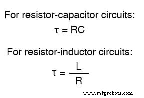
Next, compute the circuit’s time constant, the period over which the quantity shifts about 63 % from its starting to its final value during a transient. In a series RC circuit, τ = R × C. For a series L/R circuit, τ = L / R. The time constant is measured in seconds and denoted by the Greek letter τ (tau).
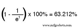
Voltage and current in a transient response follow exponential curves that asymptotically approach their final values. After one τ, the quantity has moved approximately 63 % closer to its goal. The exact percentage is given by:

Using Euler’s constant e (≈ 2.71828), the percentage change after n τs is:
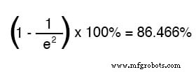
After two τs:
After ten τs:
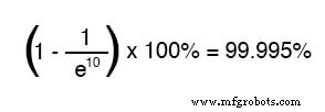
As time increases, the fraction in the exponential term shrinks, driving the overall expression toward 1 (100 %).
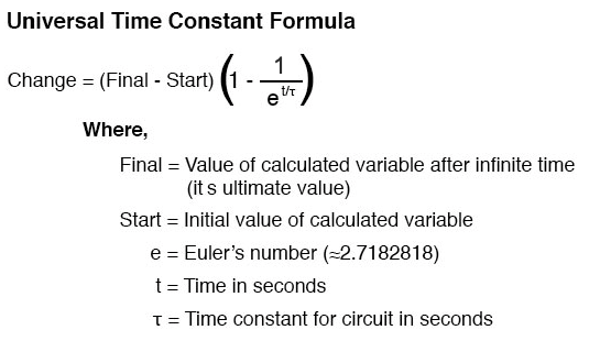
Universal Time Constant Formula
For a concise calculation, multiply the exponential term by the difference between the final and initial values:
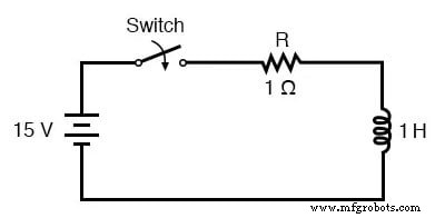
Let’s apply this to the series RC circuit shown earlier.
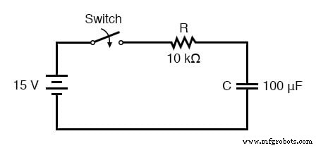
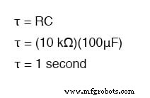
Because a capacitor resists voltage change, we analyze voltage directly. The resistor is 10 kΩ and the capacitor 100 µF, yielding τ = 10 kΩ × 100 µF = 1 s.
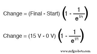
Assuming the capacitor starts discharged (0 V) and the battery supplies 15 V, the universal formula becomes:
After 7.25 s, the voltage rise is:
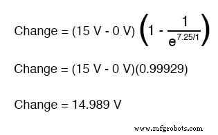
Thus the capacitor reaches 14.989 V at 7.25 s.
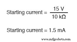
The same expression yields the current. With a freshly discharged capacitor acting as a short, the initial current is 15 V / 10 kΩ = 1.5 mA. The final current is zero once the capacitor behaves as an open circuit.
Applying the formula gives a change of –1.4989 mA, so the current at 7.25 s is 1.065 µA.
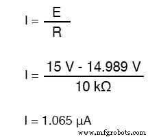
Alternatively, subtract the capacitor voltage from the battery voltage, then apply Ohm’s law: I = (15 V – 14.989 V) / 10 kΩ = 1.065 µA—confirming the result.
Using the Universal Time Constant Formula for Inductive Circuits
The same approach works for RL circuits. Consider the example L/R circuit with L = 1 H and R = 1 Ω; τ = L / R = 1 s.
Here the reactive element opposes current change. Starting with the switch open, the current is zero. After a long time, the steady‑state current is V / R = 15 A.
To find the current at 3.5 s, use the universal formula:
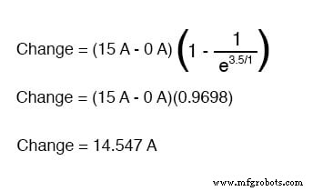
Since the initial current is zero, the current at 3.5 s is 14.547 A.
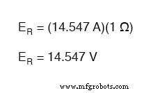
Voltage across the inductor is obtained by subtracting the resistor drop from the supply. With a single 1 Ω resistor, the drop is 14.547 V, leaving 0.453 V across the inductor at 3.5 s.
Review
- Universal Time Constant Formula: ΔQ = (Q_final – Q_initial) · (1 – e^(–t/τ))
- Steps for RC or RL analysis:
- 1. Compute τ (RC or L/R).
- 2. Identify the reactive quantity (voltage for capacitors, current for inductors).
- 3. Determine initial and final values.
- 4. Insert values into the universal formula and solve for the change.
- 5. If the initial value is zero, the computed change equals the quantity at time t; otherwise, add the change to the initial value.
Related Worksheets
- Time Constant Circuits Worksheet
- Time Constant Calculations Worksheet
Explore our collection of Power Calculators in the Tools section.
Industrial Technology
- Understanding Voltage and Current: The Foundations of Electrical Flow
- Voltage and Current in a Practical Circuit: Understanding Their Relationship
- Ohm’s Law Explained: How Voltage, Current, and Resistance Interact in Electrical Circuits
- Understanding Insulator Breakdown Voltage and Dielectric Strength
- Capacitors & Calculus: How Voltage Change Drives Current
- Advanced Analysis of DC Reactive Circuits with Non‑Zero Initial Conditions
- Comprehensive Summary of Resistors, Inductors, and Capacitors in AC Circuits
- Understanding Mutual Inductance and Transformer Fundamentals
- Retrieve Current Date and Time in Python: A Practical Guide
- Takt Time, Cycle Time, and Lead Time Explained: Key Definitions, Calculations, and Production Impact