


AC Capacitor Circuits: Capacitive Reactance, Phase Shift, and Power Behavior
Capacitors vs. Resistors
Unlike resistors, which permit current proportional to the voltage drop, capacitors resist changes in voltage. They absorb or supply current as they charge or discharge to a new voltage level.
Current flowing "through" a capacitor is directly proportional to the rate of change of the voltage across it—an effect known as reactance. This behavior is the opposite of the inductive reactance observed in inductors.
Capacitor Circuit Characteristics
The relationship between current and voltage change is expressed mathematically as:
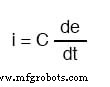
Here, de/dt (or dv/dt) denotes the rate of change of instantaneous voltage (volts per second), C is capacitance in Farads, and i is current in Amps.
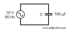
To illustrate these concepts, consider a simple AC‑only circuit:
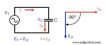
In a pure capacitive circuit, the capacitor voltage lags the current by 90°.
Plotting the voltage and current reveals a 90° phase difference:
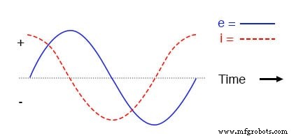
Waveforms in a pure capacitive circuit.
The instantaneous current is zero when the voltage reaches a peak (no change). It reaches its maximum when the voltage slope is steepest, i.e., at the zero crossings. Consequently, the current leads the voltage by 90°, and the voltage lags behind the current.
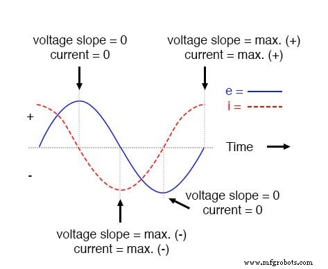
Voltage lags current by 90° in a pure capacitive circuit.
The power relationship mirrors that of inductors: the instantaneous power oscillates between positive and negative values. A capacitor does not dissipate power; it merely exchanges energy with the circuit.
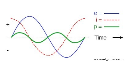
Instantaneous power alternates between positive and negative in a pure capacitive circuit.
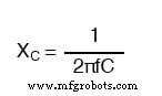
Capacitive Reactance
Capacitors oppose voltage changes, which translates to reactance against AC voltage—a quantity measured in ohms and denoted as XC. Because current is proportional to the voltage rate of change, a capacitor conducts more current at higher frequencies and less at lower frequencies.
Thus, capacitive reactance is inversely proportional to frequency:
Reactance of a 100 µF Capacitor
| Frequency (Hz) | Reactance (Ω) |
|---|---|
| 60 | 26.5258 |
| 120 | 13.2629 |
| 2500 | 0.6366 |
Unlike inductive reactance—which increases with frequency—capacitive reactance decreases. The equation can be written as XC = 1/(2πfC) = 1/(ωC), where ω is angular frequency in radians per second.
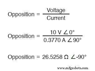
In a simple series circuit, AC current equals the applied voltage divided by the capacitive reactance, just as Ohm’s law applies to resistors:
Because voltage and current are out of phase, the phase angle of capacitive reactance is –90°. This negative imaginary component is crucial for analyzing complex AC networks that combine resistance and reactance.
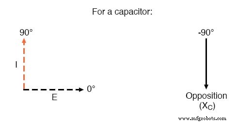
Voltage lags current by 90° in a capacitor.
Key Takeaways
- Capacitive reactance (XC) opposes AC and is measured in ohms.
- It is calculated as XC = 1/(2πfC) and decreases as frequency increases.
- Current leads voltage by 90°, resulting in a phase angle of –90° for the reactive component.
- Capacitors store and release energy without dissipating power.
Further Learning
Industrial Technology
- Power Supply Circuits: Types, Design Principles, and Performance
- Understanding Power in Electric Circuits: Measurement & Significance
- Voltage Divider Circuits: Mastering Series Resistor Analysis & Potentiometers
- Understanding Insulator Breakdown Voltage and Dielectric Strength
- Understanding Capacitor Transient Response: Charging Dynamics, Asymptotic Behavior, and SPICE Simulation
- Understanding Instantaneous Values in Pure AC Resistor Circuits
- Understanding AC Inductor Circuits: Reactance, Phase Shift, and Power Dynamics
- Analyzing Series Resistor‑Inductor AC Circuits: Impedance, Phase, and SPICE Verification
- Pure Resistive AC Circuits: Voltage and Current In Phase
- Electric Pendulum: How Capacitors and Inductors Exchange Energy