


How to Wire a Double 3-Way Combination Switch Device: A Complete Installation Guide
Installation of Double Three-Way Switch Combo Device for Common & Separated Feed
What is a Double 3-Way Combo Switch Device?
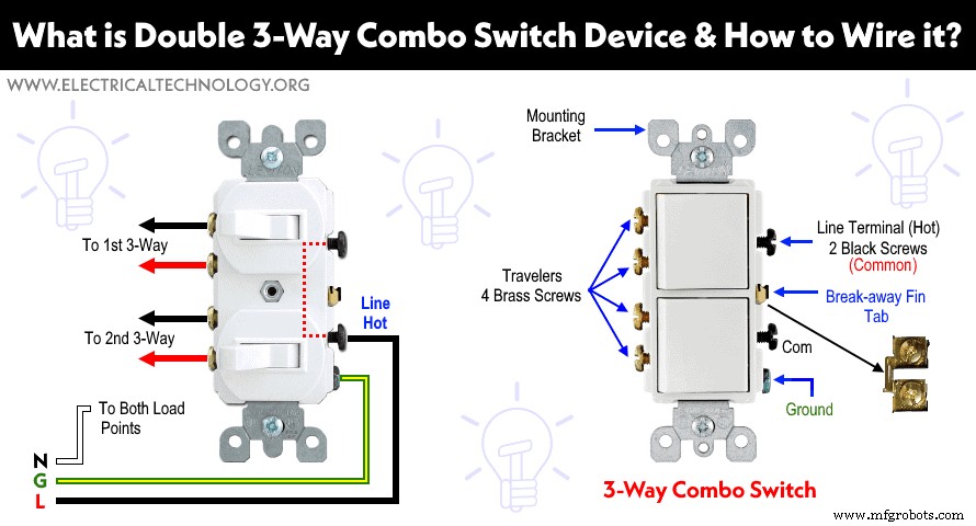
A Three-Way combo switch device is actually the combination of two 3-way switches in a single unit (such as Leviton 5243, 5640, 5643 etc.) It can be used for 120V and 240V circuits where a load point (e.g. light bulb) needs to be controlled from two different places with the help of an additional ordinary 3-way switch. Moreover, It can be used as double switch for ON/OFF switch for lighting circuits.
Construction of Double 3-Way Combo Device
The following figure shows the basic construction of a double 3-Way combination switch. It has a total of 7 terminal screws. The four brass screws are for travelers wires while the two black screws are common (hot) which is bonded together by a break-off fin. The break-away fin can be removed to use two separate incoming sources from two different breakers. The green colored screw is used for Grounding wire. Since switches are wired on Hot conductors, there is no need of a silver screw for Neutral wire.
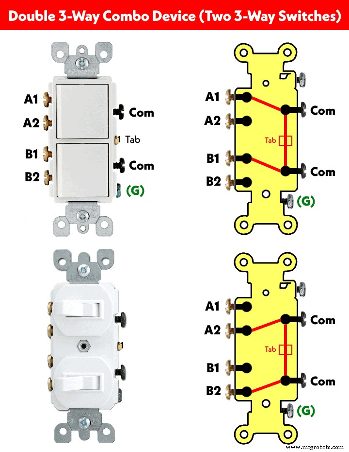
The following figures show the operation of internal contacts in a double three-way combo switch device (combination of a 3-way switches).
Let’s see how to wire these types of switches for different load circuits and applications.
Wiring Double 3-Way Combo Switch Device as Ordinary Double Pole Switch
The following wiring shows a double three-way switch is used as double switch to control two different bulbs for single operation (like two way switch) . To do this, just connect the common of the double 3-way switch (any one of the dark screws on the right) to the Hot wire. Now connect the upper brass screw (number 1) and lower brass screw (number 3) to two different light bulbs. Connect the ground and neutral wires to the bulbs as well.
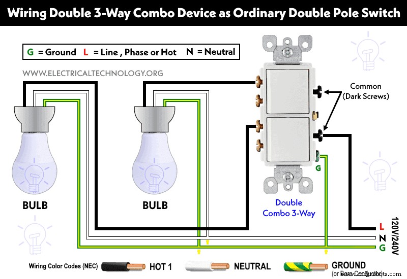
This way, the double 3-way switch can be operated like a double switch for ON and OFF operation same as single pole SPST switch.
Controlling Two Bulbs From Different Places using Double 3-Way Switches
The following wiring diagram shows that two numbers of bulbs are wired and controlled from two different places using two double 2-way switches. As shown, the hot from the breaker is connected to the common (dark screw) of the first double 3-way switch). The A1, A2, B1 and B2 terminals (brass screws) of both double 3-way switches are connected through travelers wires.
The break-away fin of the second double 3-way switch has been removed and the upper and lower dark screws are connected to two separate bulbs. Finally, Neutral and earth are wired to the light bulbs. This way, both bulbs can be controlled from two different locations using double 3-way switches.
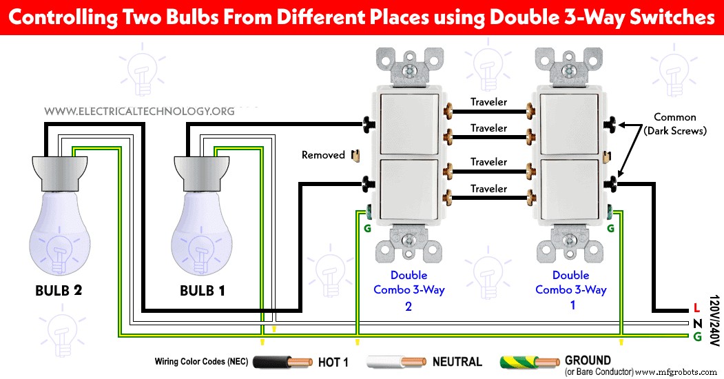
Keep in mind that you can control a single light bulb using the above wiring e.g. you may only connect the upper dark screw to a light bulb where the lower dark screw of the second double 3-way switch and its terminals of B1 and B2 are unused.
Wiring Double Combination Switch Device with Two Ordinary 3-Way Switches using Common Feed
The following wiring diagram shows how to control two light bulbs from two different places using a double 3-way combination switch and two numbers of ordinary 3-way switches using common feed. It clearly shows that the incoming Hot (Line) wire is connected to the common dark screws of combo switch that are bonded together via break-off tab.
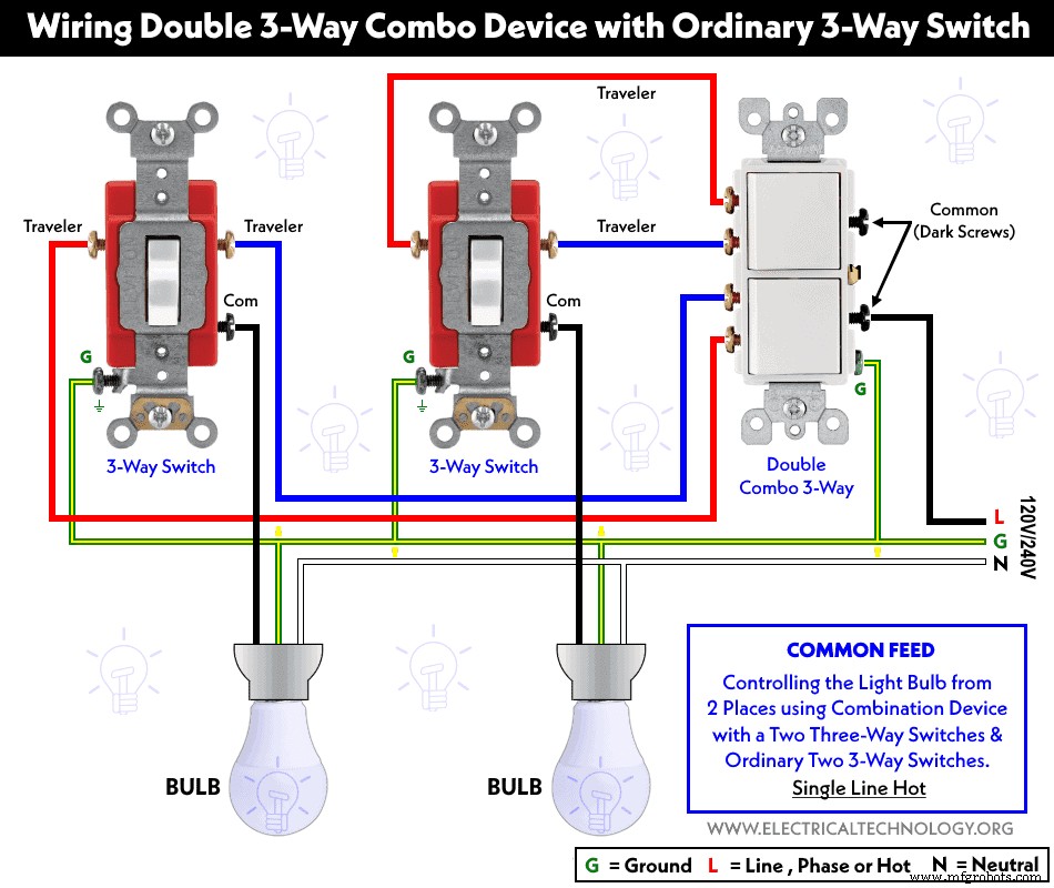
The upper two brass terminals of the double 3-way combo device are wired to the A1 and A2 terminals of a 1st typical 3-way switch via travelers wires. Similarly, the lower two brass terminals of three-way combo switch are wired to the second ordinary 3-way switch via travelers wires. The common terminals of both ordinary 3-way switches are connected to two light bulbs as shown below.
The ground wires are connected to all three switches and a light bulbs. This way, both light bulbs can be controlled for ON and OFF operations from two different locations.
Wiring Double 3-Way Combo Switch Device with Ordinary 3-Way Switches using Separate Feed
The following wiring diagram shows how to control a bulb from two different locations using a double 3-way combo device and typical 3-way switches using separate feed (2 Hot lines).
The wiring diagram is the same as above except the break-away tab is removed from the common terminal side of the double 3-way combo device. Hence, one screw is connected to Hot 1 (120V from a breaker) and the second dark screw is connected to Hot 2 (120V from another breaker) from the 120/240V main panel. The rest is same as above.
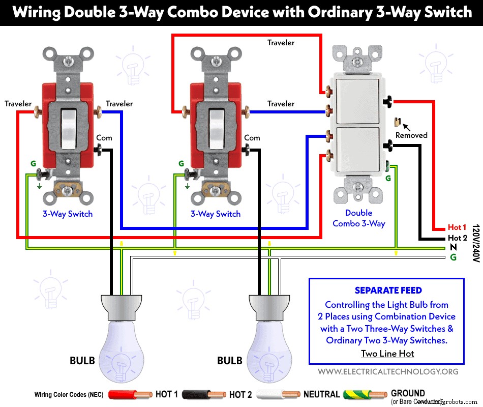
This way, fist light bulb is controlled via (HOT 1) source while the second light bulb is controlled via (Hot 2) source where both circuits can be ON and OFF from 2 different locations. The rest of the circuit and its operation is the same as above.
- The brass screws should be connected to the Hot (line, live or phase) wire using the IEC & NEC Wire color codes. In case of SPDT and 4-Way (Intermediate switches), black colored screws are used for Hot or common terminals. In short, the color for common terminal is different than other terminals.
- The silver screws should be connected to the Neutral wire (in case of switched outlet)
- The green screw should be connected to the ground / earth wire (Green/Yellow or naked wire)
- If there are no color coded screws on outlets, refer to the user manual or contact a licensed electrician.
- Neutral Wire is not required in 240V outlets wiring (US) Also, Neutral is never connected to the switches.
- Use the suitable voltage and ampere rating of switch with appropriate wire size and proper size MCB according to the load rating.
Precautions:
- Switch off the main circuit breaker to make sure the power supply is OFF before wiring an existing or new outlet or switch with an electrical/junction box.
- Contact the authorized and licensed electrician for switch installation if you are not sure about the wiring diagrams.
- The author will not be liable for any losses, injuries, or damages from the display or use of this information or if you try any circuit in the wrong format. So please! Be careful because it’s all about electricity and electricity is too dangerous.
Industrial Technology
- Step-by-Step Guide to Wiring a GFCI Combo Switch and Outlet: Diagrams & Installation Tips
- Professional Wiring Guide for Combo Switch/Outlet Devices – Diagrams & Installation Tips
- Step‑by‑Step Guide: Wiring an AFCI Combo Switch with Diagrams
- Step‑by‑Step Guide to Wiring a 3‑Way Combo Switch with Grounded Outlet
- How to Wire a Double Switch (2‑Gang, 1‑Way) – IEC & NEC Guide
- Wiring 4‑Way (NEC) or Intermediate (IEC) Switches as 3‑Way: A Step‑by‑Step Guide
- Mastering DPDT Switch Wiring: Step-by-Step Guide for 120V/240V Control
- Professional Guide to Wiring a DPST Switch for 120V/240V Circuits
- Step‑by‑Step Guide to Wiring an SPDT (Single Pole Double Throw) 3‑Way Switch
- How to Wire a Double-Acting Hydraulic Pump: Step-by-Step Guide