


Professional Guide to Wiring a DPST Switch for 120V/240V Circuits
How to Wire an DPST Switch? Controlling 120V/240V & 230V Circuit using Double Pole, Single Throw Switches
What is Double Pole, Single Throw (DPST) Switch?
DPST stands for Double Pole, Single Throw switch. It is basically two SPST switches packed in a single unit and operated by a single handle (common for both single pole, single throw switches).
Double Pole, Single Throw switch has 4 terminals as L1, L2, L3 and L3. The L1 and L2 terminals are connected to the incoming lines (say Hot 1 and Hot 2 in case of 240V – NEC or Phase and Neutral in case of 230V – IEC) and L3 and L4 connect to the load appliances.
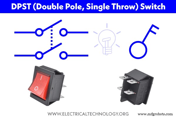
The DPST switch is the same as the 2-Poles 240 volts breaker which is used to breaker (OFF) or ON the 240V circuits via Line 1 and Line 2. Alternately, it can be used to control two circuits while the ON and OFF operation for both circuits will be the same e.g. it can only perform a single operation either ON or OFF.
The following fig shows the basic operation (Opening and Closing of both contacts) of a DPST switch rated for 120V – 277V.
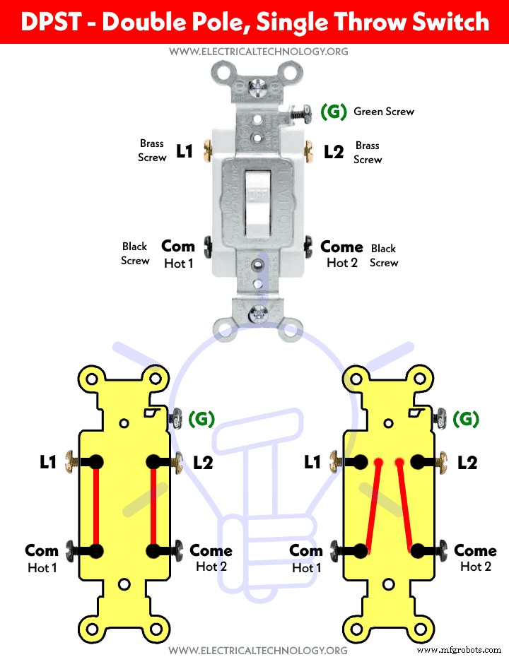
Double Pole, Single Throw (DPST) switch is used to control a 240V circuit, where both supply lines (Hot1 and Hot2) must be switched at the same time. While there is no need for a Neutral wire in 240V circuits, if so, it may be directly connected to the load point according to the user manual.
Caution: Switches are always wired on the Phase (Line or Hot) wires same as fuses.
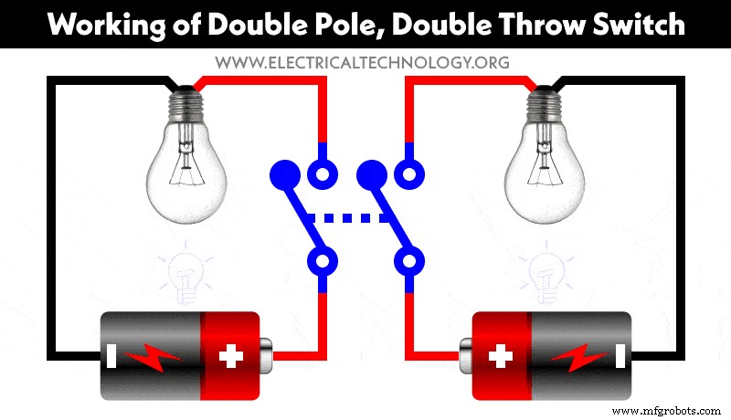
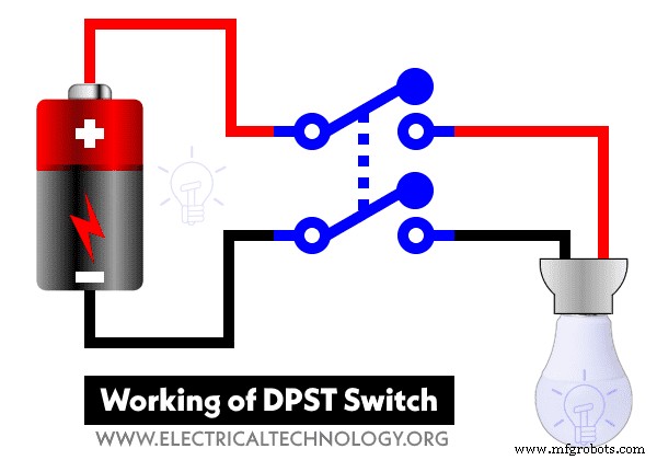
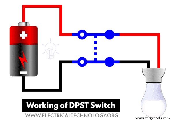
Working of DPST Switch?
The following gif and short video illustrates how a double pole, single throw switch works in the circuit.
Short Video:
Let’s see how to wire a DPST switch for different applications.
Controlling & Wiring a Light Bulb as Single Load using DPST Switch
The following wiring diagram shows an LED bulb is wired and controlled through a dual pole, single throw switch. Both the Line and Neutral can be connected as well as disconnected using the DPST switch. The wiring diagram applies on both DC and AC 230V or 120V.
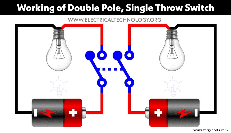
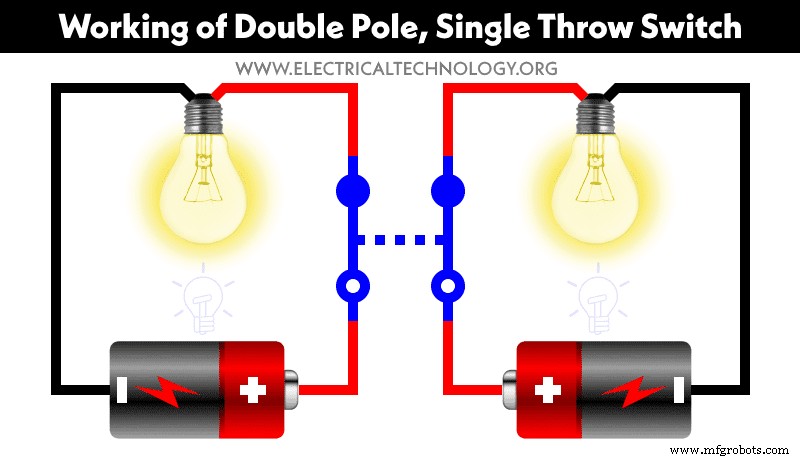
Controlling Two Light Bulb as Double Load using DPST Switch
The following wiring diagram shows two LED bulbs are wired and controlled through a DPST switch. As shown, both Lines are connected to the input terminals of double pole, single throw switch from two different sources (say Hot1 & Hot 2 or backup generator and solar panels or batteries etc.).
The Neutral wire is directly connected to the lamp holders of both lighting points. This way, both bulbs can be ON or OFF at the same time while using two different sources.
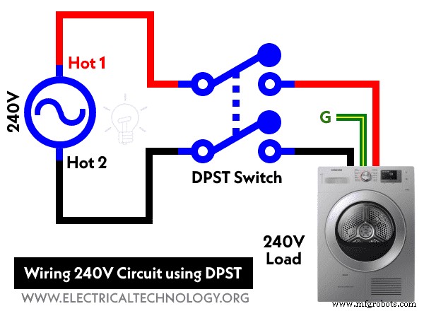
Wiring & Controlling a 240V Circuit using Double Pole, Single Throw Switch
In this wiring diagram, a 240V – AC load appliance (such as dryer, water heater etc.) is wired through a 30A DPST switch. As shown, there is no need to wire the neutral wire, hence both Hot 1 and Hot 2 wires for 240V are directly connected to the double pole, single throw switch and the load point. The ground wire is connected directly to the dryer.
The DPST switch will break both the hot wires when OFF. Similarly, it will connect both Hot wires when at ON position.
Controlling a Water Heater Using DPST Switch
The following diagram shows a water heater is wired and controlled using a double pole, single throw switch. As shown, the common (black screws) are connected to the 240V source (Hot 1 and Hot 2) from a 2-pole breaker. The L1 and L2 terminals (brass screws) are wired to the water heater. Finally, the ground wire is connected to the water heater terminal box. Keep in mind that neutral is not needed in 240V circuits.
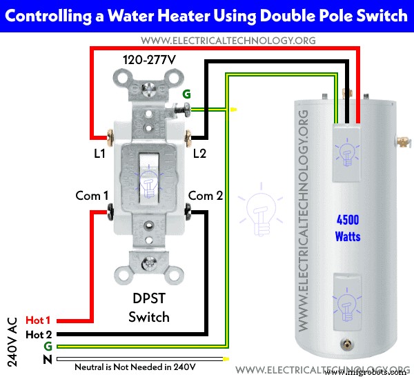
This way, the up position of the switch will ON the water heater (via both Hot wires) while the lower position will OFF the water heater. In other words, the operation of the double pole rocker will make or break both the Lines at once.
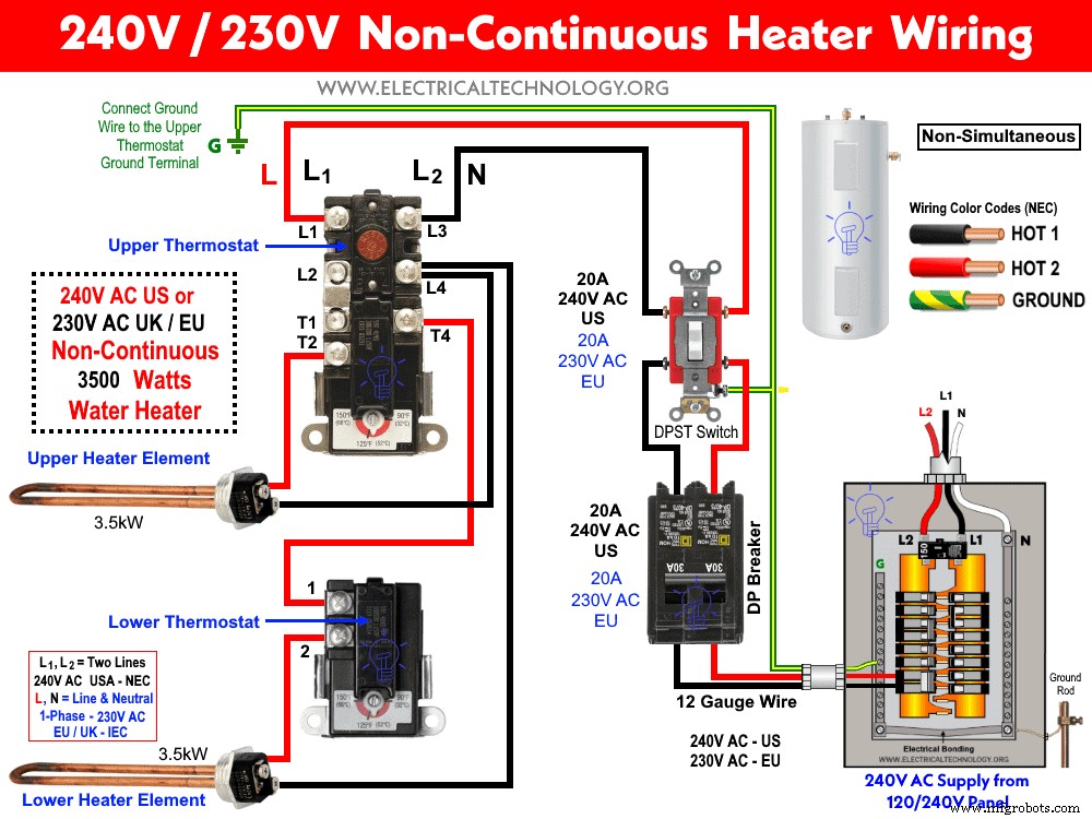
The following wiring diagram shows the wiring and controlling of 240V non-simultaneous water heater thermostat and elements using 20A DPST switch.
- The brass screws should be connected to the Hot (line, live or phase) wire using the IEC & NEC Wire color codes.
- The green screw should be connected to the ground / earth wire (Green/Yellow or naked wire)
- If there are no color coded screws on outlets, refer to the user manual or contact a licensed electrician.
- Neutral Wire is not required in 240V outlets wiring (US). Also, Neutral is never connected to the switches.
- Use the suitable voltage and ampere rating of switch with appropriate wire size and proper size MCB according to the load rating.
Precautions:
- Switch off the main circuit breaker to make sure the power supply is OFF before wiring an existing or new outlet or switch with an electrical/junction box.
- Contact the authorized and licensed electrician for switch installation if you are not sure about the wiring diagrams.
- The author will not be liable for any losses, injuries, or damages from the display or use of this information or if you try any circuit in the wrong format. So please! Be careful because it’s all about electricity and electricity is too dangerous.
Related Electrical Wiring Installations tutorials:
- How to Wire an Outlet Receptacle? Socket Outlet Wiring Diagrams
- How to Find the Number of Outlets on a Single Circuit Breaker?
- How to Find Voltage & Ampere Rating of Switch, Plug, Outlet & Receptacle
- How to Wire a Pilot Light Switch? Wiring of 2 & 3 Way Neon Light Switches
- How to Wire Combo Switch and Outlet? – Switch/Outlet Combo Wiring Diagrams
- How to Wire an AFCI Combo Switch – AFCI Switch Wiring Diagrams
- How to Wire GFCI Combo Switch and Outlet – GFCI Switch/Outlet Wiring Diagrams
- How to Control Water Heater using Switches?
- How to Wire a Ceiling Fan? Dimmer Switch and Remote Control Wiring
- How to Wire Auto & Manual Changeover & Transfer Switch – (1 & 3 Phase)
- Automatic Bathroom Light Switch Circuit Diagram and Operation
- Staircase Wiring Circuit Diagram – How to Control a Lamp from 2 Places by 2-Way Switches?
- How to Control a Lamp by a Single Way or One-Way Switch?
- How to control each lamp by separately switch in parallel lighting circuit?
- How to Control One Light Bulb from Five or Six Different Places using Intermediate Switches?
- Corridor Wiring Circuit Diagram – Hallway Wiring using 2-Way Switches
- Hospital Wiring Circuit for Light Control using Switches
- Hostel Wiring Circuit Diagram and Working
- Godown Wiring Diagram -Tunnel Wiring Circuit and Working
- Tunnel Wiring Circuit Diagram for Light Control using Switches
- How to Wire a UK 3-Pin Plug? Wiring a BS1363 Plug
- How to Wire a UK 3-Pin Socket Outlet? Wiring a BS1363 Socket
- How to Wire a Twin 3-Pin Socket Outlet? Wiring 2-Gang Socket
- How to Wire Combo Switch and Outlet? – Switch/Outlet Combo Wiring Diagrams
- Switch and Push Button Symbols
- Basic Electrical Wiring Diagrams
Industrial Technology
- Step-by-Step Guide to Wiring a GFCI Combo Switch and Outlet: Diagrams & Installation Tips
- Step‑by‑Step Guide to Wiring 2‑Way & 3‑Way Neon Pilot Light Switches
- Professional Wiring Guide for Combo Switch/Outlet Devices – Diagrams & Installation Tips
- Step‑by‑Step Guide: Wiring a Household Outlet Receptacle with Clear Diagrams
- Step‑by‑Step Guide: Wiring an AFCI Combo Switch with Diagrams
- How to Wire a Double 3-Way Combination Switch Device: A Complete Installation Guide
- How to Wire a Double Switch (2‑Gang, 1‑Way) – IEC & NEC Guide
- Mastering DPDT Switch Wiring: Step-by-Step Guide for 120V/240V Control
- Step‑by‑Step Guide to Wiring an SPDT (Single Pole Double Throw) 3‑Way Switch
- Step-by-Step Guide: Wiring an SPST (Single Pole, Single Throw) as a 2-Way Switch