


Wiring 4‑Way (NEC) or Intermediate (IEC) Switches as 3‑Way: A Step‑by‑Step Guide
How to Wire an Intermediate Switch as Three-Way Switching & Wiring Crossover Switch as Four-Way Switching – IEC & NEC
What is 4-Way Switch and 3-Way Switch – NEC & IEC?
There is no difference between 4-way switch (NEC) and 3-Way switch IEC e.g. it represents the same thing.
- North America – US: It is known as the 4-Way Switch or Crossover Switch. The pair of wires connecting the two switches (4-Way & 3-Way) are known as travelers.
- UK, EU & IEC following Countries: It is known as 3-Way Switch or Intermediate Switch. The pair of wires connecting the two switches (3-Way & 2-Way) are known as strappers.
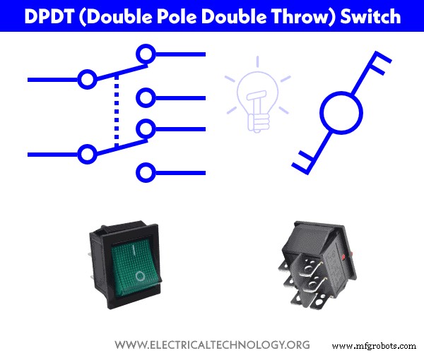
In short, a 4-Way Switch (US) or 3-Way (Intermediate) Switch is a DPDT is a “Double Pole Double Throw” switch having four terminals.
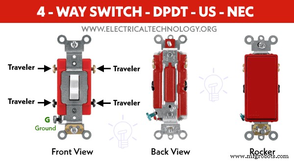
4 – Way Switch – DPDT, Double Pole, Double Throw – US – NEC
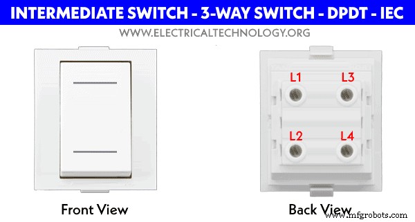
3 – Way Switch – DPDT, Double Pole, Double Throw – UK – IEC
Difference Between 4-Way and Double Pole Switches (US – NEC).
- Both 4-Way switch and Double Pole switch look similar and have 4 terminals screws The device rating differentiate them. Alternatively, the switch terminals can be tested using a multimeter in the continuity test mode.
- 4-Way switches are rated for 120V – 277V, while double pole switches are rated for 220V to 240V.
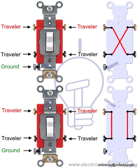
- 4-Way switch divert both wires when switch position is changed, while double pole switch turns ON or OFF both wires.
- When switch position is changed, the 4-Way switch diverts (interchanges) both wires while double pole switch turns ON or OFF both wires.
What is DPDT Switch?
DPDT (stands for Double Pole Double Throw) switch is used to control two different circuits at the same time e.g. home appliances such as lighting circuits etc. Due to the common lever, it is used to control a single operation either ON or OFF between two electric circuits such as corridor or staircase wiring installation where a lighting point is controlled from more than two places.
DPDT switch has 6 terminals where 2 of them are used as common while the rest are used as travelers or signal pins.
Good to know: DPDT switch is known as double pole, double throw, crossover switch or 4-way switch in North America (US – NEC). While it is known as three Way switch or intermediate Switch in the Europe, UK and IEC following countries.
What is Intermediate Switch?
Intermediate switch is known as 3-Way switch in the UK and IEC following countries, while it is known as crossover or 4-way switch in North America and US.
The 4-way switch has four terminals (for travelers wires) plus ground terminals in the US. While in the UK, it has only four terminals namely L1, L2, L3 and L4.
The main four terminals are used to divert the flow of electric current from one position to another. For this reason, 4-Way switches (intermediate switches) are used to control a single circuit from more than two locations such as 2-way & Three way switching circuits, hallway & corridor wiring, hostel wiring, hospital wiring, tunnel wiring, godown wiring, staircase wiring etc.
Intermediate (or 4-Way Switch) can be used to control a lighting point from any number of locations. For example, if we need to control a light bulb from six places, we will need four numbers of 4-way switches and two numbers of 3-way switches.
 Caution: Switches are always wired on the Phase (Line or Hot) wires same as fuses. In addition, 4-Way Switches (Intermediate Switches) are a little bit expensive due to the complex internal configuration.
- Related Post: What is Intermediate Switch (3-Way in IEC) A.K.A 4-Way Switch in NEC?
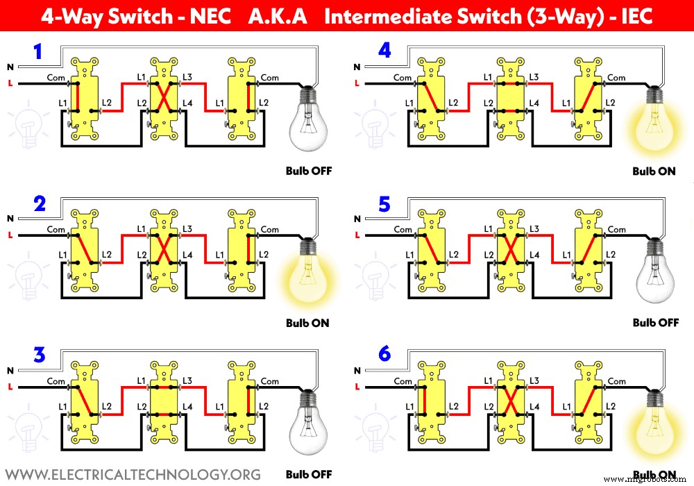
The following fig and gif shows how is a 4-way switch working with 3-way switches to control an LED lamp from three different locations (alternately, 3-way switch wired with 2-way switches to control a lamp from 3 places – according to IEC).

Here is the short video format.
Let’s know how how to wire three-way and four-way switches one by one for different load points according to NEC and IEC.
The above wiring diagrams are shown as a schematic diagram using symbols as below.
Wiring 4-Way Switch (DPDT) for 120V/240V Circuits – NEC
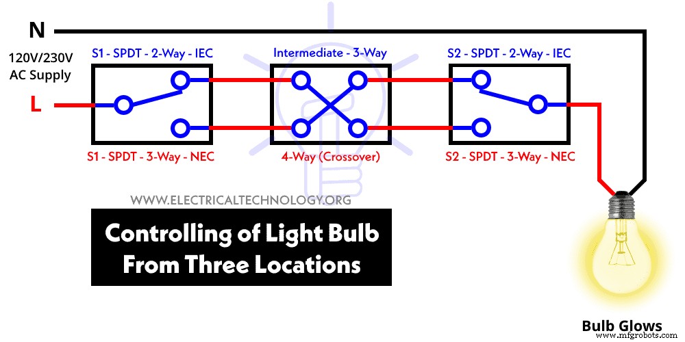
How to Control a Light Bulb from Three Different Places using 4-Way and 3-Way Switches?
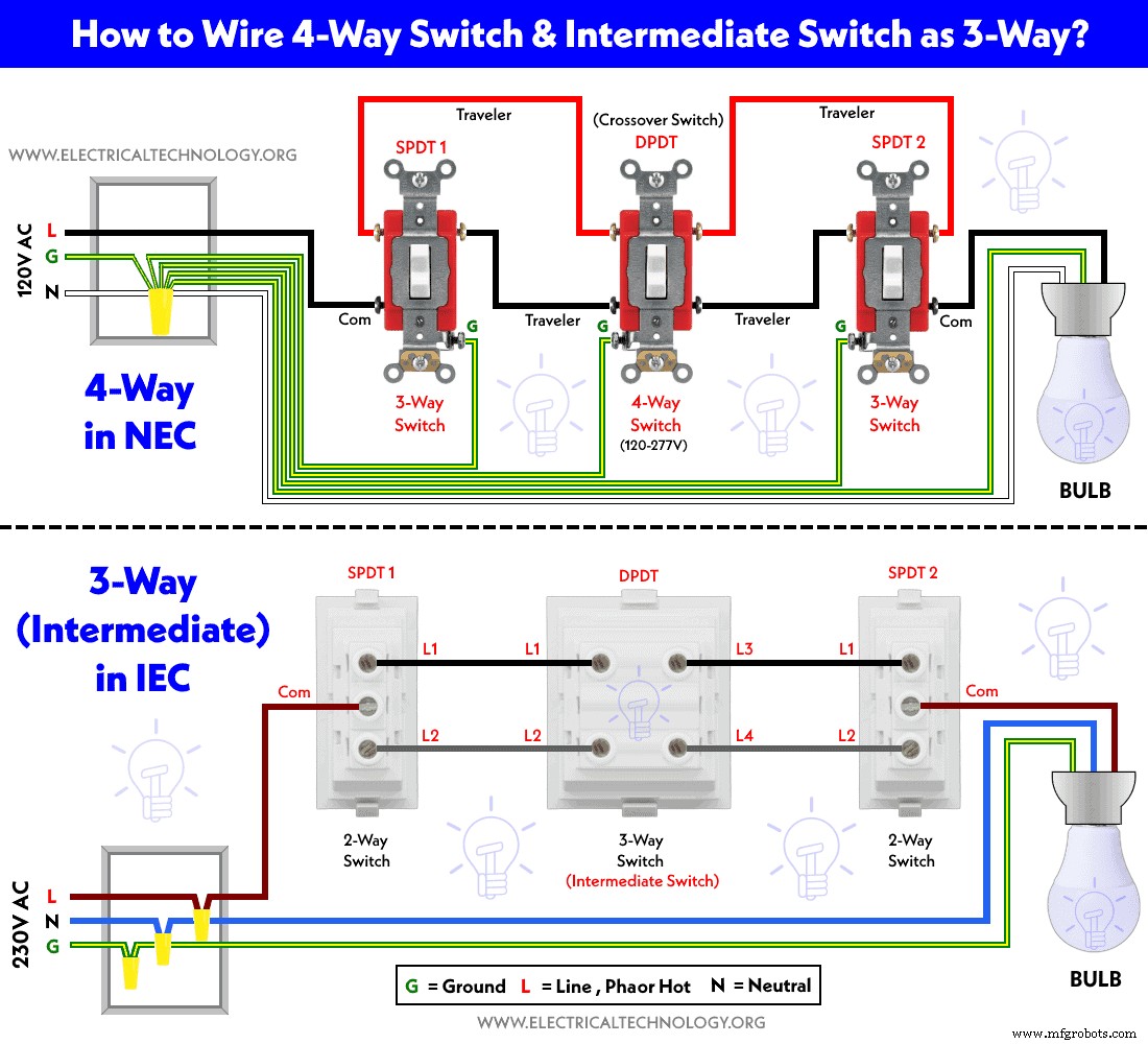
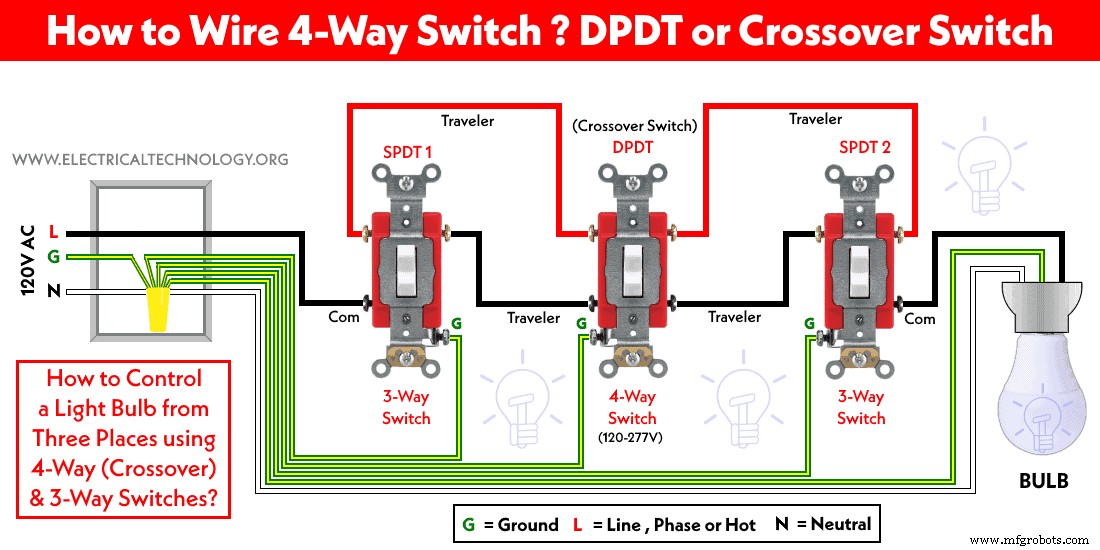
The following wiring diagram shows that a light bulb is wired and controlled from three different places using the DPDT and SPDT switches. As shown, there are three incoming wires from the breaker in the electrical box e.g. L (Line or Hot), N (Neutral) and G (Ground).
To control the light bulb from three different places, we need two, 3-Way switches and one 4-way switch.
The ground wire is connected to the Ground terminals of both (1st and last) 3-way switches as well as the 4-way switch (Green with yellow stripe). The incoming Line (as hot) is connected to the line terminal (common as black screw) of the first 3-way switch. The brass terminals of the 3-way switch are connected to the first pair of terminal screws of the 4-way switch via travelers wires. The second pair of terminal screws of the 4-way switch is connected to the travelers wires to the brass terminals of the second 3-way switch.
The common terminal of the second 3-way switch is connected to the light bulb holder. Keep in mind that neutral wire is never connected to the switches.
Finally, the neutral and ground wire is directly connected to the lamp holder. This way, the lamp can be controlled for ON/OFF operation from three places.
Keep in mind that you can control the light point from any number of locations. For example, in the following wiring diagram, a light bulb is controlled from five different locations using three numbers of 4-way switches and two numbers of 3-way switches.

Wiring 3-Way (Intermediate) DPDT Switch for 230V Circuits – IEC
How to Control a Light Bulb from Three Different Locations using 3-Way (Intermediate) and 2-Way Switches?
In the following wiring diagram for 230V AC supply system – IEC, two 1-gang two way switches and an intermediate switch (3-way) is used to control a light bulb from three different locations. The fig shows that the incoming Phase (Line) wire (brown Color) is connected directly to the common terminal of the first 2-way switch. The L1 and L2 terminals of both 2-way switches are connected through strappers (Black & Gray) Wires to the L1, L2 & L3, L4 terminals of 3-way switch respectively. The common terminal of the second 2-way switch is connected to the bulb holder.
Finally, the Neutral (Blue) and Ground (Green with yellow stripe) is connected to the light bulb holder.
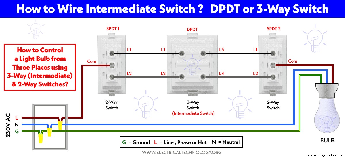
This way, the light bulb can be controlled for ON and OFF operations from three different places using two-way switches and 3-way switches i.e. intermediate switches.
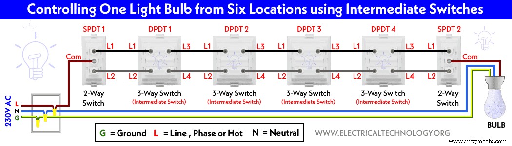
Keep in mind that you can control the light point from any number of locations. For example, in the following wiring diagram, a light bulb is controlled from six different locations using 4 numbers of intermediate switches and two numbers of 2-way switches.
- Double Pole & 4-Way Switches look similar but they are different. Both have 4 terminal screws. Keep in mind that double poles switches are rated for 220V to 240V while 4-Way switches are always rated for 120V to 277V. In addition, when the position of the 4-way switch is changed, it reverses both wires to opposite terminals and when the position of the double pole switch is changed, it turns both wires On or OFF. It is recommended to check the device rating or at least check using a multimeter in continuity test mode to verify the terminals.
- The brass screws should be connected to the Hot (line, live or phase) wire using the IEC & NEC Wire color codes. In case of SPDT and 4-Way (Intermediate switches), black colored screws are used for Hot or common terminals. In short, the color for common terminal is different than other terminals.
- The silver screws should be connected to the Neutral wire (in case of switched outlet)
- The green screw should be connected to the ground / earth wire (Green/Yellow or naked wire)
- If there are no color coded screws on outlets, refer to the user manual or contact a licensed electrician.
- Neutral Wire is not required in 240V outlets wiring (US) Also, Neutral is never connected to the switches.
- Use the suitable voltage and ampere rating of switch with appropriate wire size and proper size MCB according to the load rating.
Precautions:
- Switch off the main circuit breaker to make sure the power supply is OFF before wiring an existing or new outlet or switch with an electrical/junction box.
- Contact the authorized and licensed electrician for switch installation if you are not sure about the wiring diagrams.
- The author will not be liable for any losses, injuries, or damages from the display or use of this information or if you try any circuit in the wrong format. So please! Be careful because it’s all about electricity and electricity is too dangerous.
Industrial Technology
- Professional Wiring Guide for Single-Phase kWh Meters – 120V/240V (NEC) & 230V AC (IEC)
- Step-by-Step Guide to Wiring a Ceiling Fan: Dimmer Switches, Remote Controls, and Compliance with IEC & NEC Standards
- Step-by-Step Guide to Wiring a GFCI Combo Switch and Outlet: Diagrams & Installation Tips
- Professional Wiring Guide for Combo Switch/Outlet Devices – Diagrams & Installation Tips
- Step‑by‑Step Guide: Wiring a Household Outlet Receptacle with Clear Diagrams
- Step‑by‑Step Guide: Wiring an AFCI Combo Switch with Diagrams
- How to Wire a Double 3-Way Combination Switch Device: A Complete Installation Guide
- Step‑by‑Step Guide to Wiring a 3‑Way Combo Switch with Grounded Outlet
- How to Wire a Double Switch (2‑Gang, 1‑Way) – IEC & NEC Guide
- Step‑by‑Step Guide to Wiring an SPDT (Single Pole Double Throw) 3‑Way Switch