


Understanding Single‑Phase Induction Motors: Types, Operation, and Efficiency Improvements
Understanding Single‑Phase Induction Motors
Single‑phase induction motors are ubiquitous in residential and light industrial applications, yet their operation differs significantly from their three‑phase counterparts. This article explains why a single‑phase motor cannot self‑start, outlines the various auxiliary winding strategies that enable reliable operation, and discusses modern power‑factor correction techniques that improve efficiency.
Why a Three‑Phase Motor Fails on Single‑Phase Power
When a three‑phase motor is connected to a single‑phase supply, it can be hand‑started in either direction and will accelerate to full speed in a few seconds. However, it will only reach about 2/3 of its rated power because one of the three windings is effectively unused. The motor produces a pulsating magnetic field rather than a rotating one, so no self‑starting torque is generated.

Single‑Coil Operation and the Need for an Auxiliary Winding
The single coil of a single‑phase induction motor generates a non‑rotating, pulsating magnetic field. Two counter‑rotating phasors are produced, aligning only at 0° and 180° electrical, resulting in no starting torque. If the rotor is spun manually to slightly below synchronous speed, maximum torque occurs at about 10% slip relative to the forward rotating phasor. Once the motor starts, the auxiliary winding becomes optional.
Single‑phase induction motors typically feature a copper or aluminum squirrel‑cage rotor within a steel lamination shell, similar to polyphase motors.
Permanent‑Split Capacitor Motor
By adding a second winding 90° electrical apart and feeding it with a 90° phase‑shifted current, a two‑phase motor is effectively created from single‑phase supply. This configuration is known as a permanent‑split capacitor (PSC) motor.
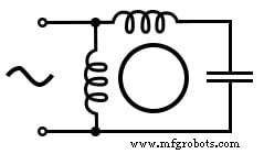
PSC motors deliver higher starting torque and smoother running characteristics up to 1/4 hp (200 W). The capacitor is kept small to minimize losses and can be reversed to change motor direction.
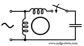
Capacitor‑Start Induction Motor
In larger motors, a sizable capacitor is placed in series with an auxiliary winding that is removed by a centrifugal switch once the motor reaches operating speed. This arrangement yields high starting torque, making it ideal for heavy‑load applications such as air‑conditioning compressors.
Capacitor‑Run Induction Motor
A variation of the capacitor‑start design uses a large starting capacitor and a smaller running capacitor. The smaller capacitor reduces running losses while maintaining a near‑rotating magnetic field.
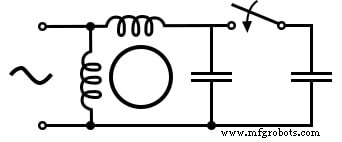
Starting capacitors are often electrolytic and must be used only intermittently due to high losses. Running capacitors are polymer or ceramic to keep losses low during continuous operation.
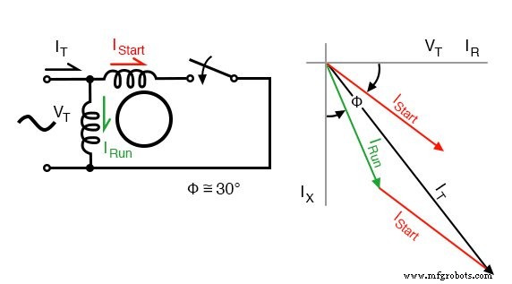
Resistance‑Split‑Phase Motor
When a secondary winding with fewer turns and higher resistance is placed 90° electrical apart, it creates a 30° phase shift during startup. The auxiliary winding is disconnected by a centrifugal switch at ¾ of synchronous speed. This simple, capacitor‑free design is suitable for motors up to 1/3 hp (250 W).
Power‑Factor Correction for Single‑Phase Motors
Frank Nola of NASA introduced a power‑factor corrector in the 1970s to address the low power factor of lightly loaded induction motors. By sensing the power factor and reducing the applied voltage, the device restores a higher power factor and reduces core losses.
While three‑phase motors already offer superior efficiency, single‑phase motors can achieve 2–4× better performance when operated near full load. For motors that idle frequently or operate at low loads (≤ 25% full load), a power‑factor controller can yield noticeable energy savings, especially in equipment such as conveyors or heavy‑load pumps.
Key Takeaways
- Single‑phase motors require an auxiliary winding and a phase‑shifted current to start.
- Permanent‑split capacitor motors use a capacitor both at startup and running.
- Capacitor‑start motors provide high starting torque but use the capacitor only during startup.
- Capacitor‑run motors use a large start capacitor and a smaller run capacitor.
- Resistance‑split‑phase motors generate a phase shift via differing resistance, offering moderate starting torque without a capacitor.
Related Resources
Industrial Technology
- Build a Permanent Capacitor Split-Phase Induction Motor – Step‑by‑Step Guide
- Build a Large-Scale AC Permanent Split‑Capacitor Induction Motor
- Stepper Motors: Types, Characteristics, and Practical Applications
- Brushless DC Motors: Design, Construction, and Advanced Applications
- Tesla Polyphase Induction Motors: Design, Operation, and Applications
- Wound‑Rotor Induction Motors: Design, Advantages, and Variable‑Speed Applications
- Specialized Motors: Shaded‑Pole, Servo, Hysteresis, and Eddy‑Current Clutch Applications
- Understanding AC Commutator Motors: Design, Types, and Applications
- Extending Motor Life: Expert Maintenance Tips
- Running a Three‑Phase Induction Motor from a Single‑Phase Power Supply: Proven Methods and Tips